APV_CU4 AS-i_UK-5_072018.indd
UK
Control Unit
CU4 AS-interface
Instruction manual: UK - rev. 5
APV
32
8. CU Assembly and Startup
8.2.3 Startup
After proper assembly and installation of the control unit, startup can
be undertaken as described below:
1. Switch on the air supply.
2. Switch on the voltage supply.
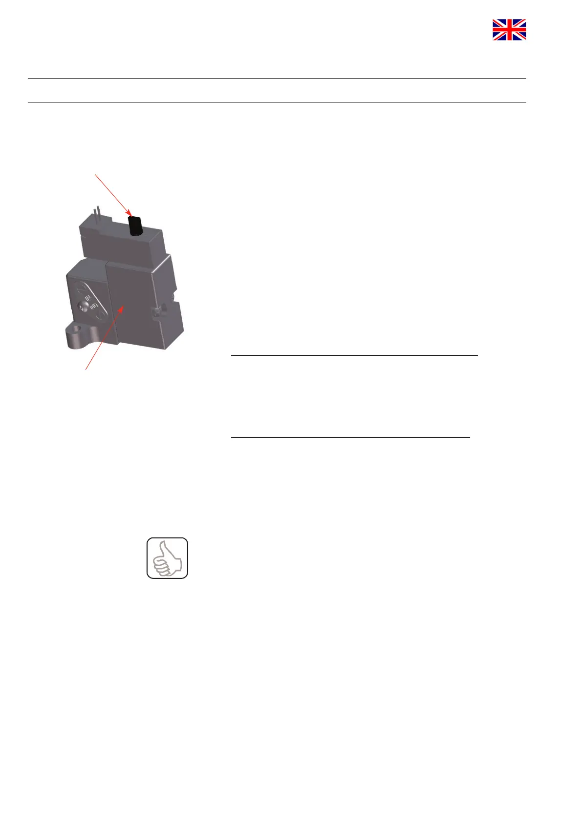
3. Check the solenoid valves by turning the lever on the upper side of
the valve by 90°.
4. Check the valve position indicator and adjust feedbacks for open
and closed valve position as described below
Forsingleseatvalvesinnormallyclosed(normallyopen)
thefollowingallocationapplies:
Closedvalvepositionfeedback–sensor1controlled
For the adjustment, Hall sensor 1 with non-controlled(controlled)
solenoid valve 1 is moved into the required position by turning the
adjustment screw 1. The LED Valve Closed lights up.
Openvalvepositionfeedback–sensor2controlled
FortheadjustmentofHallsensor2,atrst,the(non-controlled)
solenoid valve 1 is controlled. This can optionally be made
manually or electrically. The open valve position and the
corresponding feedback can be adjusted. This is undertaken by
turning the adjustment screw 2 until the required position is reached
and the LED Valve Open lights up.
ObservetheswitchinghysteresisoftheHalleffectsensors!
Therefore,adjusttheswitch-pointofthesensorswithoverlap
inordertopermitsmallvariationsand,thus,toprevent
failures!
lever
solenoid valve
 Loading...