8. CU Assembly and Startup
8.4.3 Connectionofexternalproximityswitches
Theelectricconnectionoftheproximityswitchesspeciedby
SPX FLOW is undertaken according to the terminal layout
described in chapter 6.1.
The mechanic assembly of the proximity switches is carried out
at the actuator of the corresponding double seat valves.
Observance of the instruction manual for double seat valves
is essential!
8.4.4 Startup
After proper assembly and installation of the control unit, startup
can be undertaken as described below
1. Switch on the air supply
2. Switch on the voltage supply.
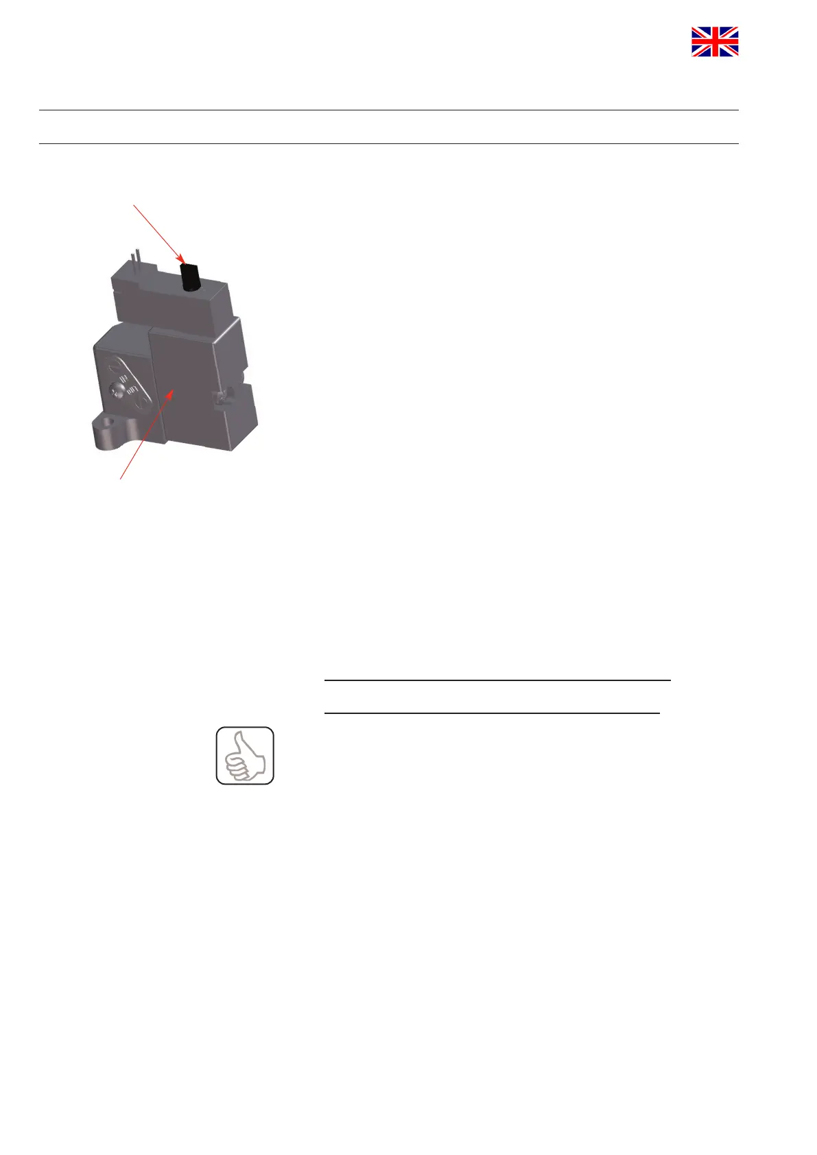
3. Check the solenoid valves by turning the lever on the upper side
of the valve by 90°.
4. Check the valve position indicator.
The proximity switches are installed at the double seat valves
with a mechanical stop.
Adjustment is not required!
Thefollowingallocationappliesfordoubleseatvalves:
Closedvalvepositionfeedback–sensor3controlled
Openvalvepositionfeedback–sensor2controlled
Checktheproperfitoftheproximityswitchestoprovidefor
theaccuratetransferofthesignalsforthecorresponding
valve position.
lever
solenoid valve
APV_CU4 AS-i_UK-5_072018.indd
UK
Control Unit
CU4 AS-interface
Instruction manual: UK - rev. 5
APV
38
 Loading...