12
381497 USA 10-2014
APV
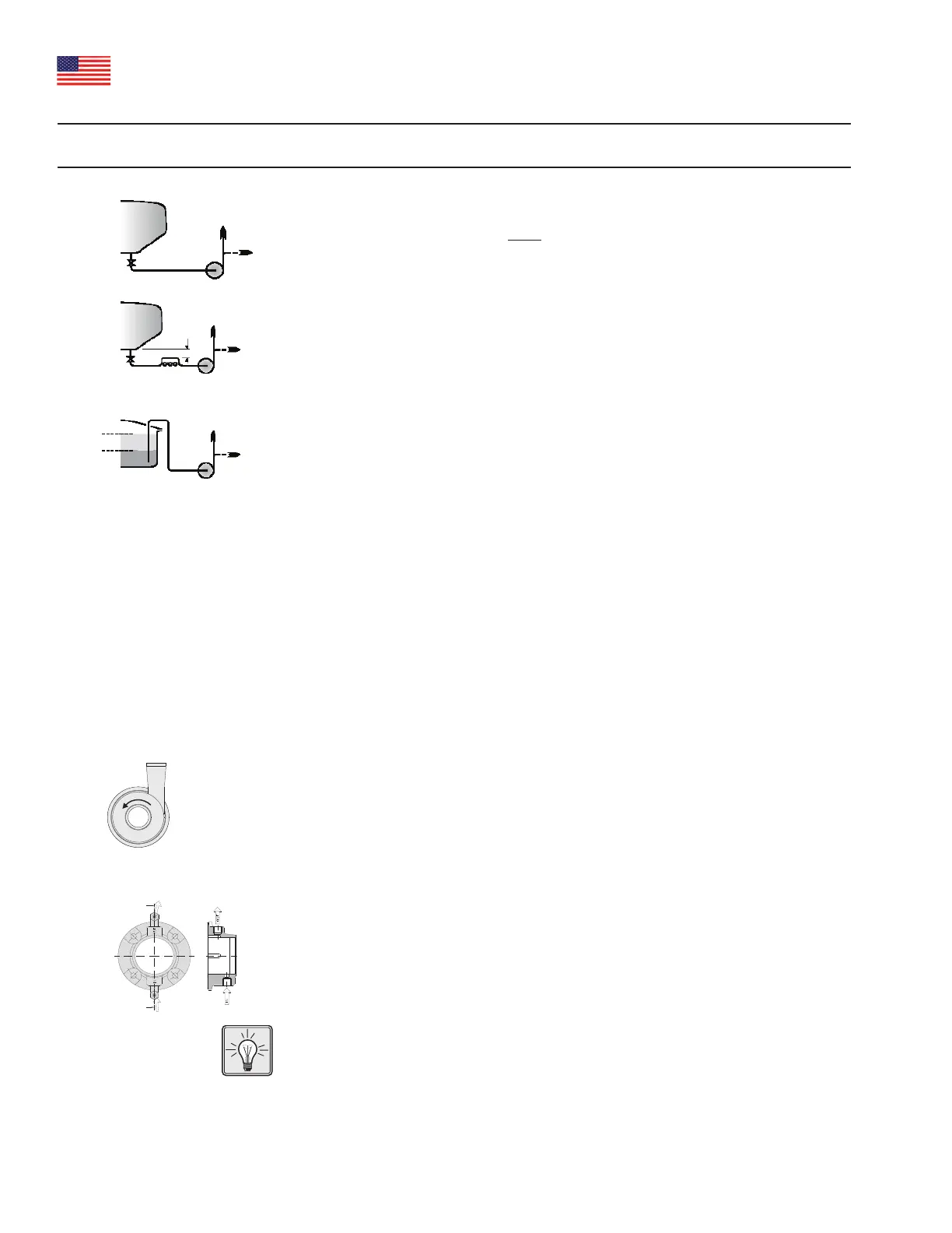
2.3 Installation of pump without recirculation.
In this application, where the simplified pipe layout is to be used, one
important requirement must be met:
As the suction tank starts to refill, some liquid will be able to flow from
the tank into the pump to replenish any priming liquid lost when the
tank was previously pumped dry. Typical applications can be seen in
Fig. 3.
Note: The pump body must always be mounted with outlet vertically
upwards and all the other conditions apply.
Note: Any eccentric reducer should be mounted such that the pump
center line is lower than the inlet pipe's center line.
2.4 Lining up the pipe system
Line up the pipes carefully to the pump suction and discharge ports.
Make sure that the pipe system is adequately supported by pipe
supports, so that the pump body is not subject to strains and weight
from the pipe system.
Note: During priming the pump may tend to vibrate. A pipe support
should be placed close to the pump suction to prevent pipework
vibration creating excessive noise.
2.5 Power supply
All electrical installation must comply with all applicable codes and
standards including those established by the Occupational Safety and
Health Administration (OSHA).
Install a main power disconnect on-off switch that can be locked in the
power off position and have the key removed when service is
performed.
Thoroughly read the motor manufacturer’s instructions before making
installation.
The motor should be connected such that the rotating direction of the
motor (and thus of the impeller) is counterclockwise when viewed from
the front towards the suction nozzle of the pump body (Fig. 4).
2.6 Water supply for water-flushed shaft seal
Pumps with a water-flushed shaft seal have two hose connectors on
the seal flange (Fig. 5). The hose connectors are 1/8 inch NPT and fit a
1/4 inch plastic tubing. A flush flow of 4-8 gallons/h is required.
Maximum pressure is 100 PSIG.
The hose connection in the seal flange should always be positioned
vertically with the fluid inlet underneath and the outlet on top.
Water consumption can be limited by installing a solenoid valve for the
flushing water on the supply side. The open/close function of the
solenoid valve can be controlled by the pump's start/stop sequence.
Before starting the pump, dismantle and clean the suction pipe. Any
foreign material in the pump must be removed.
(A)
(B)
(C)
20”
min.
Liquid level
High
Low
Fig. 3: Typical applications
Fig. 4: Direction of rotation
Fig. 5: Water flush hose connections
2. Installation of the pump