16
381497 USA 10-2014
APV
16. After fitting, clean the wearing surfaces.
For liquid-flushed, re-mount the back plate.
17. Fit the impeller. Check that the location pin (item 8, where fitted) in
the top of the back plate, mates with the detent in the pump body
and carefully, to avoid damaging the o-ring, press the pump/screw
housing (item 1) in over the o-ring (item 6). Fasten with the clamp
ring (item 9). See "Required torques for housing clamp" table on
page 18.
18. Re-mount the air screw. Remember to use the proper tightening
torque:
M14: 52 lb·ft (70 Nm)
M20: 148 lb·ft (200 Nm)
19. Press the front cover into place and fit the clamp ring.
Re-assemble the re-circulation connection (if fitted).
5.3 Replacement of motor
The standard motor for the Ws+ pump has a locked front bearing. If the
motor is replaced, the new motor must also have a locked front
bearing. The motor bearing is enclosed and permanently lubricated.
Follow the instructions below when replacing the motor. For
replacement of bearings, see the motor supplier's service instructions.
1. Lock Out power supply then disconnect the pump and motor from
system.
2. Remove of the front cover, air screw, pump/screw housing and
impeller (items 27, 2, 1 and 4) described as in para. 5.2, points
1-5 on page 14.
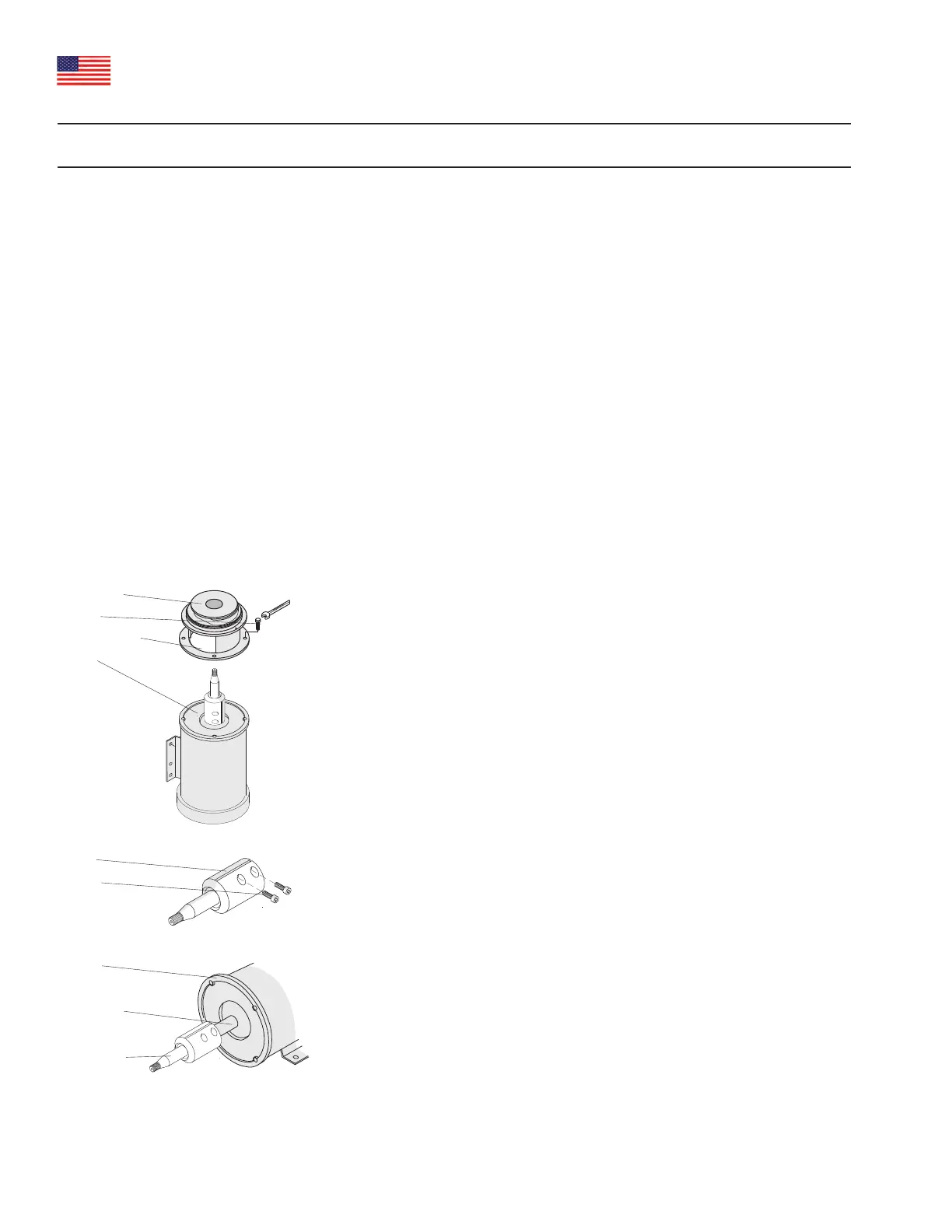
3. If possible, stand the pump on end. See Fig. 8.
4. Undo the four motor flange bolts and remove them. See Fig. 8.
5. Lift the backplate (item 7) and extension frame (item 14), which
are still bolted together, up and off the shaft. See Fig. 8.
Remove the washer (item 17), if supplied.
6. See Fig. 9. Loosen the screws in the shaft muff, pull the shaft off
and replace the motor.
7. See Fig. 8. Before re-mounting the pump shaft, remove any dirt
and grease from the motor shaft and the muff's internal clamping
surfaces. Mount the pump shaft loosely. Position the balance hole
over the keyway.
8. Fit the back plate and extension frame over the shaft.
9. Tighten the bolts.
10. Stand the pump back on its legs/bracket.
11. Fit the impeller and secure it temporarily with the nut (M14 or
M20) which is supplied as a tool with the pump.
5. Maintenance
Back plate
Screw
Extension frame
Motor
Fig. 8: Unscrew motor flange bolts
Fig. 9: Loosen screws
Shaft
Screw
Fig. 7: Mount pump shaft
Motor
Motor shaft
Pump shaft
Note: for numbered items,
see assembly drawing on
page 8.
Note: for numbered items,
see assembly drawing on
page 8.