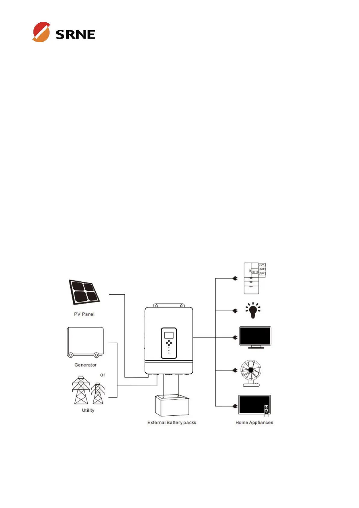
2.3 System connection diagram
The diagram below shows the system application scenario of this product. A complete system consists
of the following components:
1. PV modules:converts light energy into DC energy, which can be used to charge the battery via an
inverter or directly inverted into AC power to supply the load.
2. Utility grid or generator:connected to the AC input, either of the connected utility and generator can
charge the battery while supplying the load. When the batteries and photovoltaic modules supply the
load, the system can operate without the utility or generator.
3. Battery:The role of the battery is to ensure the normal power supply of the system loads in case of
insufficient photovoltaic and no utility power.
4. Home load:connects to a variety of home and office loads including refrigerators, lamps, TVs, fans,
air conditioners and other AC loads.
5. Inverter:it is the energy conversion device of the whole system.
The actual application scenario determines the specific system cabling.