UM1670 Rev 4 19/32
UM1670 Hardware layout
31
6.7 USB OTG supported
The STM32F429ZIT6 drives USB OTG High-Speed through its internal PHY, which limits it
to USB OTG Full Speed on this board. The USB Micro-AB connector (CN6) allows the user
to connect a host or device component, such as a USB key, mouse, or other.
Two LEDs are dedicated to this module:
• LD5 (green LED) indicates when VBUS is active
• LD6 (red LED) indicates an overcurrent from a connected device
6.8 Gyroscope MEMS (ST-MEMS I3G4250D)
The I3G4250D is a low-power, three-axis angular rate sensor. It includes a sensing element
and an IC interface able to provide the measured angular rate to the external world through
the I
2
C/SPI serial interface.
The I3G4250D has a full-scale of ±245/±500/±2000 dps and is capable of measuring rates
with a user-selectable bandwidth.
The STM32F429ZIT6 controls this motion sensor through the SPI interface.
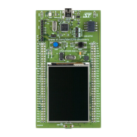
6.9 TFT LCD (Thin-film-transistor liquid-crystal display)
The TFT LCD is a 2.4" display of 262 K colors. Its definition is QVGA (240 x 320 dots) and is
directly driven by the STM32F429ZIT6 using the RGB protocol. It includes the ILI9341 LCD
controller and can operate with a typical 2.8
V voltage.
6.10 64-Mbit SDRAM (1Mbit x 16-bit x 4-bank)
The 64-Mbit SDRAM is a high-speed CMOS, dynamic random-access memory designed to
operate in 3.3
V memory systems containing 67,108,864 bits. It is internally configured as a
quad-bank DRAM with a synchronous interface. Each 16,777,216-bit bank is organized as
4,096 rows by 256 columns by 16 bits. The 64-Mbit SDRAM includes auto-refresh, power-
saving, and power-down modes. All signals are registered on the positive edge of the clock
signal, CLK.
The STM32F429ZIT6 reads and writes data at 80 MHz.
6.11 JP3 (Idd)
Jumper JP3, labeled Idd, allows the consumption of STM32F429ZIT6 to be measured by
removing the jumper and connecting an ammeter.
• Jumper ON: STM32F429ZIT6 is powered (default).
• Jumper OFF: an ammeter must be connected to measure the STM32F429ZIT6
current, (if there is no ammeter, the STM32F429ZIT6 is not powered).