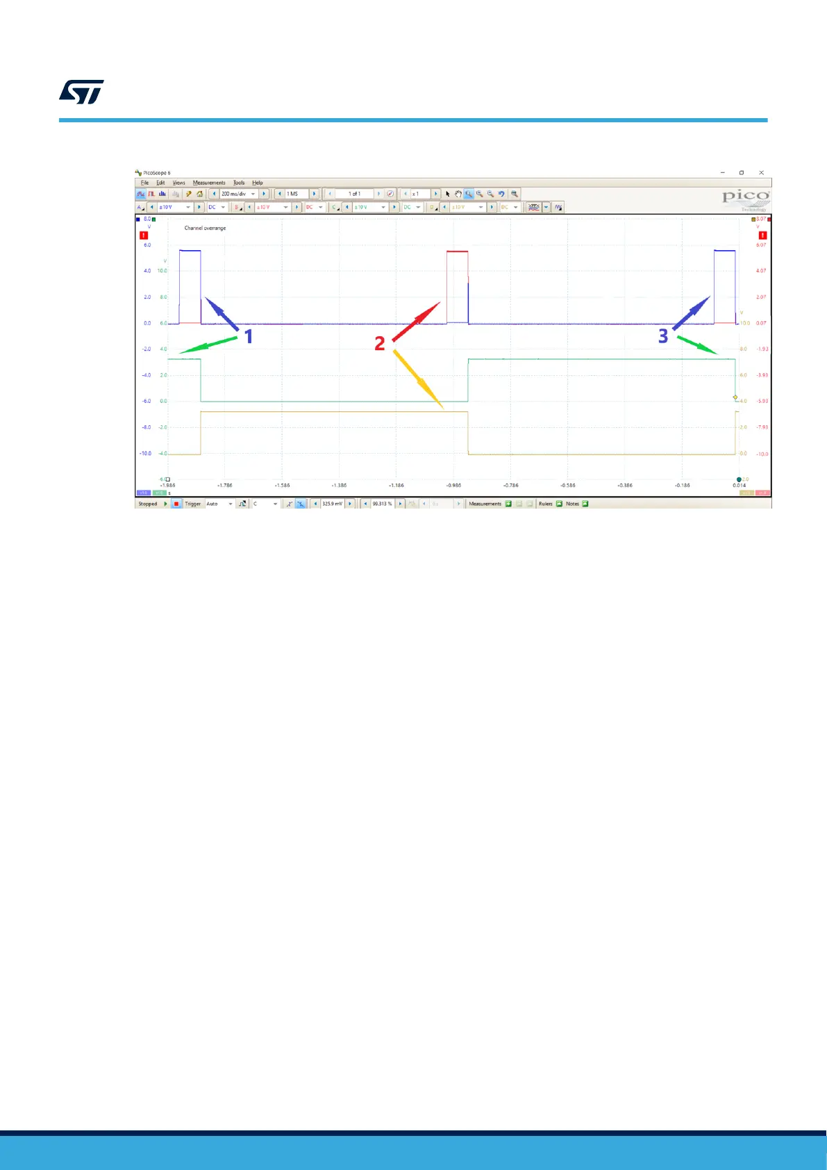
Figure 5. Presence detection waveform
4.3 Power transfer switching waveform
Once the STWBC2-HP presence detection is working correctly, you can check the power transfer switching
waveform at RING_NODE1 reference to TANK1_SEL and RING_NODE2 reference to TANK2_SEL as described
below.
1. Put the Rx coil on the Tx coil 1 and set the Rx output to 5 V. The RING_NODE1 appears sine-waved while
the RING_NODE2 is off (see Figure 6).
2. Put the Rx coil on Tx coil 2 and set the Rx output to 5 V. The RING_NODE2 appears sine-waved while the
RING_NODE1 is off (see Figure 7).
3. Put the Rx coil on the Tx coil 1 and set the Rx output to 9 V. The RING_NODE1 appears sine plus
square-waved while the RING_NODE2 is square-waved (see Figure 8).
4. Put the Rx coil on the Tx coil 2 and set the Rx output to 5 V. The RING_NODE2 appears sine plus
square-waved while the RING_NODE1 is square-waved (see Figure 9).
TN1399
Power transfer switching waveform
TN1399 - Rev 1
page 7/26