AN2586 Rev 8 11/29
Power supplies
28
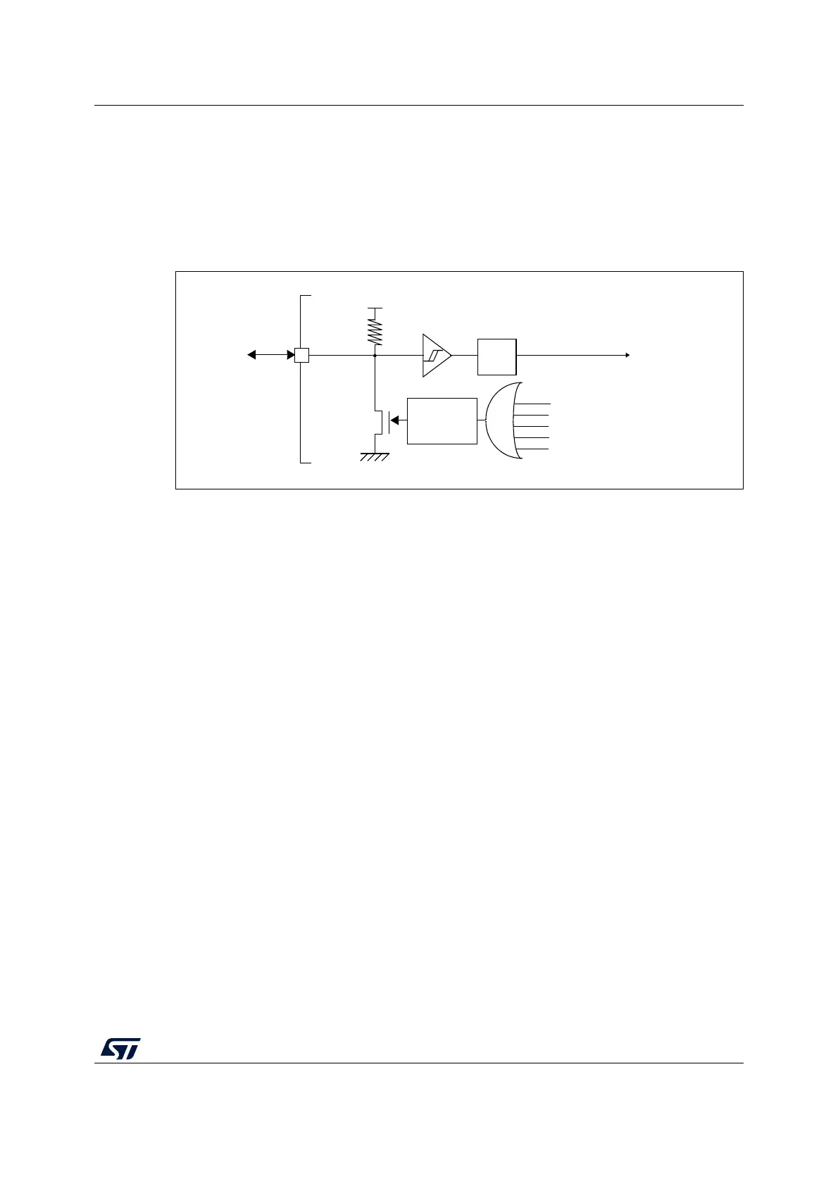
The STM32F1xx does not require an external reset circuit to power-up correctly. Only a pull-
down capacitor is recommended to improve EMS performance by protecting the device
against parasitic resets. See Figure 5.
Charging and discharging a pull-down capacitor through an internal resistor increases the
device power consumption. The capacitor recommended value (100 nF) can be reduced to
10 nF to limit this power consumption.
Figure 5. Simplified diagram of the reset circuit
NRST
R
PU
V
DD
/V
DDA
WWDG reset
IWDG reset
Pulse
generator
Power reset
External
reset
(min 20 μs)
System reset
Filter
Software reset
Low-power management reset
ai16095c
 Loading...


