Reference design
24/29 AN2586 Rev 8
7.2 Component references
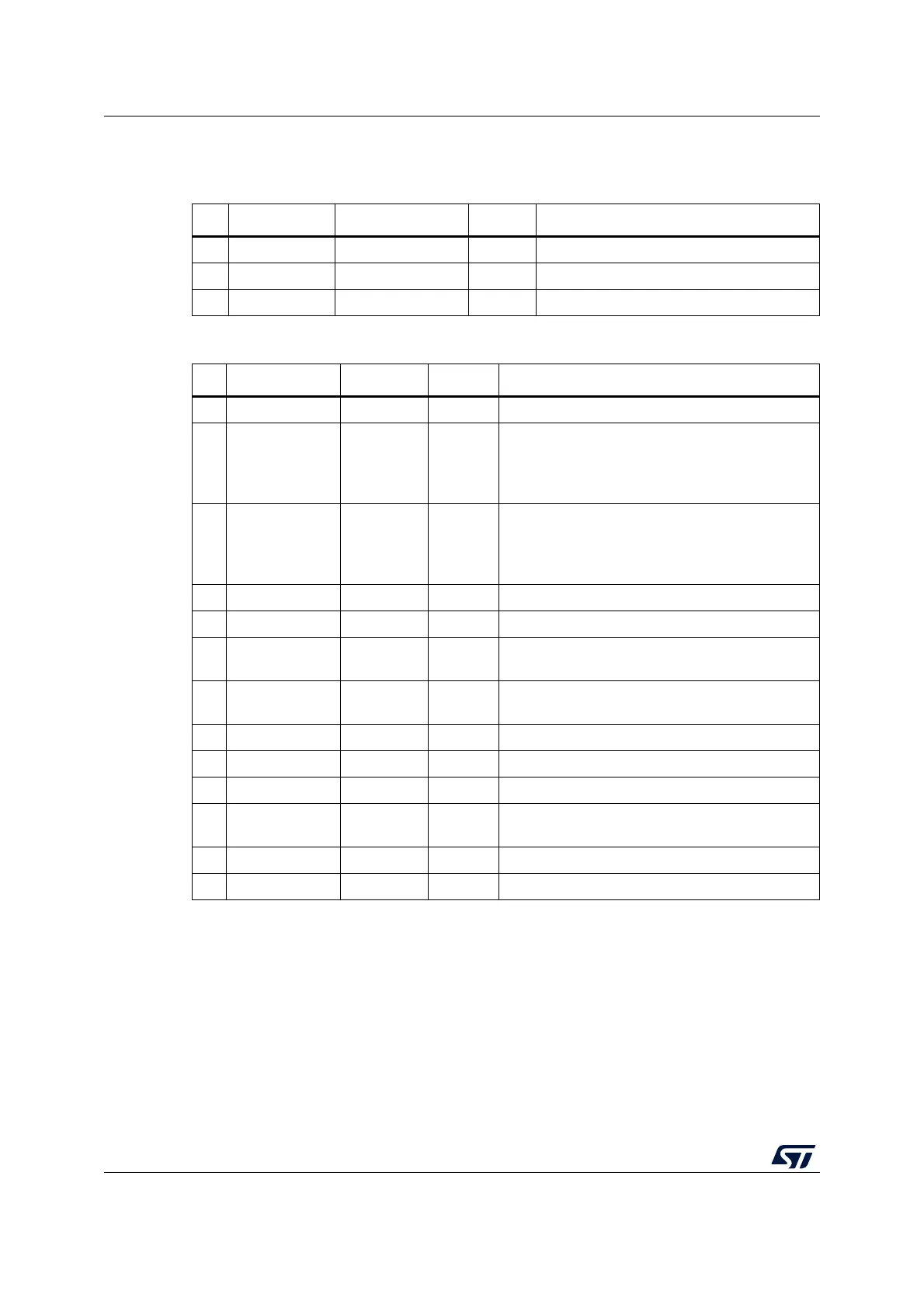
Table 5. Mandatory components
Id Name Reference Quantity Comments
1 Microcontroller STM32F103ZE(T6) 1 144-pin package
2 Capacitors 100 nF 11 Ceramic capacitors (decoupling capacitors)
3 Capacitor 10 µF 1 Ceramic capacitor (decoupling capacitor)
Table 6. Optional components
Id Name Reference Quantity Comments
1 Resistor 10 kΩ 5 Pull-up and pull-down for JTAG and Boot mode.
2 Resistor 390 Ω 1
Used for HSE: the value depends on the crystal
characteristics.
This resistor value is given only as a typical
example.
3Resistor 0 Ω 1
Used for LSE: the value depends on the crystal
characteristics.
This resistor value is given only as a typical
example.
4 Capacitor 100 nF 3 Ceramic capacitor
5 Capacitor 1µF 2 Used for VDDA and VREF.
6 Capacitor 10 pF 2
Used for LSE: the value depends on the crystal
characteristics.
7 Capacitor 20 pF 2
Used for HSE: the value depends on the crystal
characteristics.
8 Quartz 8 MHz 1 Used for HSE
9 Quartz 32 kHz 1 Used for LSE
10 JTAG connector HE10 1 -
11 Battery 3V3 1
If no external battery is used in the application, it is
recommended to connect V
BAT
externally to V
DD
12 Switch 3V3 2 Used to select the correct boot mode.
13 Push-button B1 1 -
 Loading...


