Revision history
28/29 AN2586 Rev 8
8 Revision history
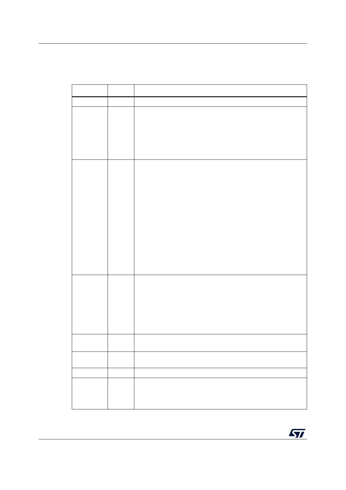
Table 8. Document revision history
Date Revision Changes
12-Jul-2007 1 Initial release.
23-May-2008 2
Application note also applicable to High-density devices.
Figure 1: Power supply overview, Figure 2: Power supply scheme and
Figure 6: Clock overview updated.
Low-speed internal RC frequency modified in Section 3: Clocks on
page 12. V
REF+
voltage range modified.
Table 7: Reference connection for all packages on page 26 added.
Small text changes.
23-Jun-2009 3
Connectivity line STM32F10xxx and Glossary added.
Section 2.2: Power supply schemes and Figure 2: Power supply scheme
updated.
Figure 5: Simplified diagram of the reset circuit updated. Figure 6 Clock
overview removed in Section 3: Clocks. Note 1 added Note 3 updated
below Figure 8: External clock. Section 3.1.1: External source (HSE
bypass) and Section 3.1.2: External crystal/ceramic resonator (HSE
crystal) updated.
Section 2.3 Clock-out capability section removed.
Section 4.1: Boot mode selection and Section 4.3: Embedded boot loader
mode updated.
When no external battery is used, it is recommended to externally
connect the V
BAT
pin to V
DD
.
PA14 updated in Table 8: Document revision history.
Small text changes.
STM3210C-EVAL evaluation board added in Section 5.
01-Mar-2010 4
This application note also applies to STM32F100xx low- and medium-
density value line products:
– low- and medium-density value line devices added to Introduction
– Section 3.1.1: External source (HSE bypass) and Section 3.1.2:
External crystal/ceramic resonator (HSE crystal) updated
– reference to value line’s evaluation board added to Section 5.1:
Introduction
Table 5: Simplified diagram of the reset circuit updated.
19-Oct-2010 5
Modified Section 3.2.1: External source (LSE bypass)
Updated for high-density value line devices.
14-Apr-2011 6
Updated VDDA and VREF schematics in Figure 14: STM32F103ZE(T6)
microcontroller reference schematic and Table 6: Optional components.
18-Nov-2011 7 Updated to include XL-density devices.
09-Dec-2022 8
Added Table 1: Applicable products and Section 1: General information.
Updated Figure 3: Power on reset/power down reset waveform, Figure 4:
PVD thresholds, and Figure 5: Simplified diagram of the reset circuit.
Minor text edits across the whole document.
 Loading...


