DocID030512 Rev 1 21/69
UM2199 Hardware layout and configuration
68
board. The signals Bootloader_RESET and Bootloader_BOOT0 are added on the RS232
connector CN2 for ISP support.
The USART1 of the STM32H753XI is shared with the RS232 of the ST-LINK/V2-1
controller. Connection is switched by setting JP7 and JP8.
8.12 microSD card
The 8-Gbyte (or more) microSD card connected to the SDIO 3.0 port of the STM32H753XI
microcontroller is available on the Evaluation board. Detection of the microSD card is
managed by MFX GPIO15.
IP4856CX25/C (M1) is an SD 3.0-compliant, 6-bit-bidirectional, dual-voltage-level translator.
It is implemented on the STM32H753I-EVAL board and it supports SD 3.0, SDR104,
SDR50, DDR50, SDR25, SDR12 and SD 2.0 in high-speed (50 MHz) and default-speed (25
MHz) modes.
8.13 External I
2
C connector
The I2C1 bus of the STM32H753XI is connected to CN4 on the STM32H753I-EVAL. The
I
2
C functional daughterboard can be mounted on the CN4 connector and accessed by the
microcontroller through the I2C1 bus.
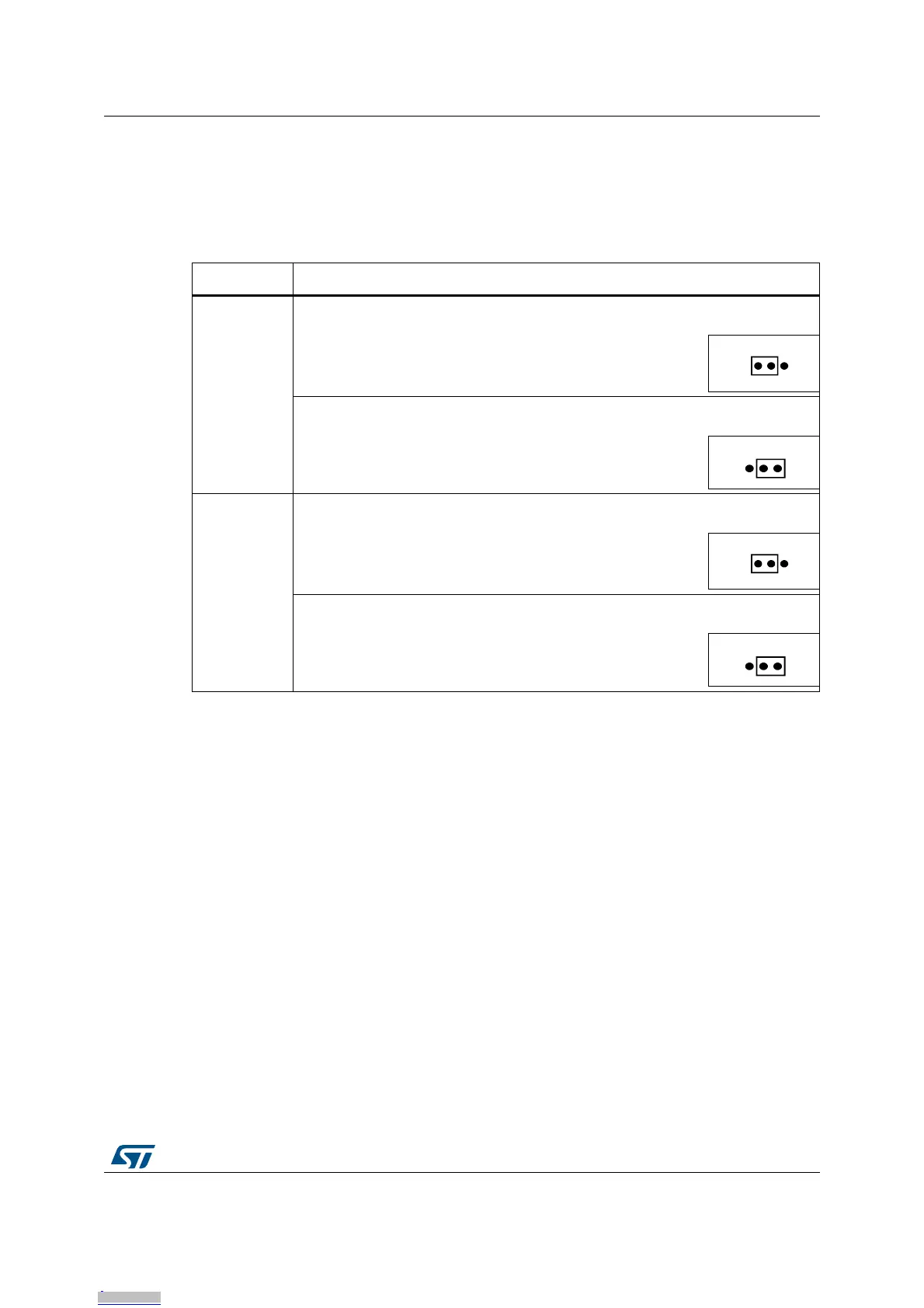
Table 10. USART1 related jumpers
Jumper Description
JP7
USART1_TX is connected to RS232 when JP7 is set as shown to the right (Default
setting):
USART1_TX is connected to the USART_RX of the ST-LINK/V2-1 controller when
JP7 is set as shown to the right:
JP8
USART1_RX is connected to RS232 when JP8 is set as shown to the right (Default
setting):
USART1_RX is connected to the USART_TX of the ST-LINK/V2-1 controller when
JP8 is set as shown to the right:
Downloaded from Arrow.com.Downloaded from Arrow.com.Downloaded from Arrow.com.Downloaded from Arrow.com.Downloaded from Arrow.com.Downloaded from Arrow.com.Downloaded from Arrow.com.Downloaded from Arrow.com.Downloaded from Arrow.com.Downloaded from Arrow.com.Downloaded from Arrow.com.Downloaded from Arrow.com.Downloaded from Arrow.com.Downloaded from Arrow.com.Downloaded from Arrow.com.Downloaded from Arrow.com.Downloaded from Arrow.com.Downloaded from Arrow.com.Downloaded from Arrow.com.Downloaded from Arrow.com.Downloaded from Arrow.com.
 Loading...


