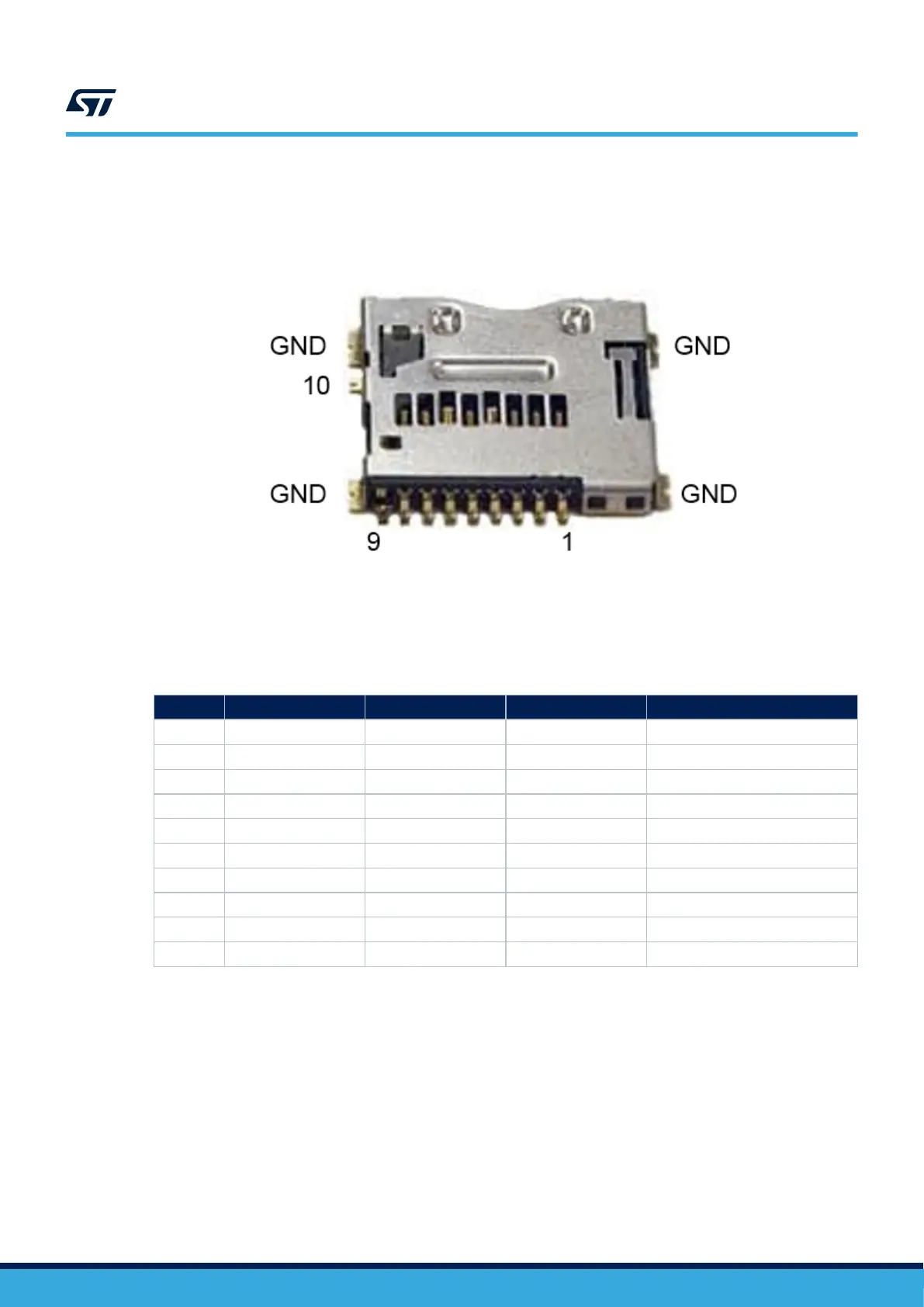
Figure 11 shows the pinout of the microSD
™
connector CN15.
Figure 11. microSD
™
card connector CN15
Table 12 describes pinout of the microSD
™
connector CN15.
Table 12. CN15 microSD
™
connector pinout
Pin
Pin name Signal name STM32 pin Function
1 DAT2 SDMMC1_D2 PC10 SDIO.D2
2 DAT3_CD SDMMC1_D3 PC11 SDIO.D3
3 CMD SDMMC1_CMD PD2 SDIO.CMD
4 3V3 3V3 - VDD_SDCARD
5 CLK SDMMC1_CLK PC12 SDIO.CLK
6 VSS GND - GND
7 DAT0 SDMMC1_D0 PC8 SDIO.D0
8 DAT1 SDMMC1_D1 PC9 SDIO.D1
9 GND GND - GND
10 CARD_DETECT uSD_DETECT PB7 SDCARD_DETECT active LOW
6.10 LEDs
6.10.1 Description
The LD2 LED turns green when the power cable is inserted in connector CN6.
Two general-purpose color LEDs (LD7 and LD8) are available as light indicators:
• The LD7 orange LED is used as STM32Cube examples verdict LED.
• The LD8 blue LED is used as Linux
®
Heartbeat LED, which is blinking as long as Linux
®
is alive on the
Cortex
®
-A.
The two user LEDs, the green LD5 and orange LD6 LEDs, are directly connected to the STM32MP157x.
UM2637
LEDs
UM2637 - Rev 2
page 17/47

 Loading...


