6.3.3 Programming and debugging the on-board MCU using the Debug_IN connector
To program the STM32 on board, plug in the Debug_IN connector (CN4) or TAG10 connector (CN2), as shown in
Figure 4. The Debug_IN connector is an Arm
®
Cortex
®
10‑pin 1.27 mm‑pitch debug connector over the STDC14/
MIPI10 footprint according to Table 5. It supports the STDC14 or MIPI10 standard connectors. The TAG10
connector pinout is shown in Table 6.
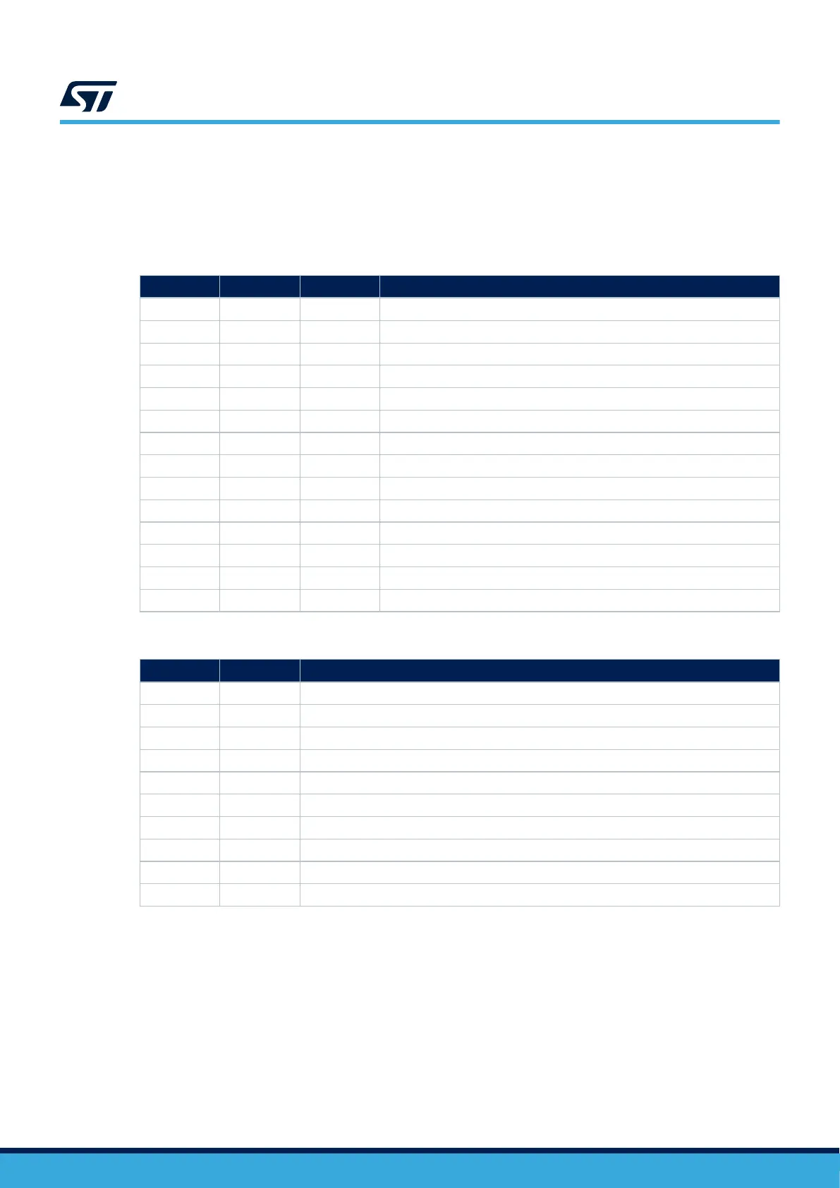
Table 5. STDC14/MIPI10 connector (CN4) (SWD only)
MIPI10 pin STDC14 pin CN4 Designation
- 1 N/A -
- 2 N/A -
1 3 VDD Target VDD from the application
2 4 SWDIO SWD data input/output
3 5 GND Ground
4 6 SWCLK SWD clock
5 7 GND Ground
6 8 SWO Reserved
7 9 SWCLK JRCLK
8 10 N/A -
9 11 GNDDetect -
10 12 NRST RESET of the target MCU
- 13 VCP_RX Target RX used for VCP (with UART supporting bootloader)
- 14 VCP_TX Target TX used for VCP (with UART supporting bootloader)
Table 6. TAG10 connector (CN2) (SWD only)
TAG
10 pin CN2 Designation
1 VDD Target VDD from the application
2 SWDIO SWD data input/output
3 GND Ground
4 SWCLK SWD clock
5 GND Ground (via SB1)
6 SWO Reserved
7 N/A -
8 N/A -
9 N/A -
10 NRST Reset of target MCU
UM3292
Hardware layout and configuration
UM3292 - Rev 1
page 11/33