6.10 Jumper configuration
The default jumper positions are shown in Table 4. Table 10 describes the other available jumper settings
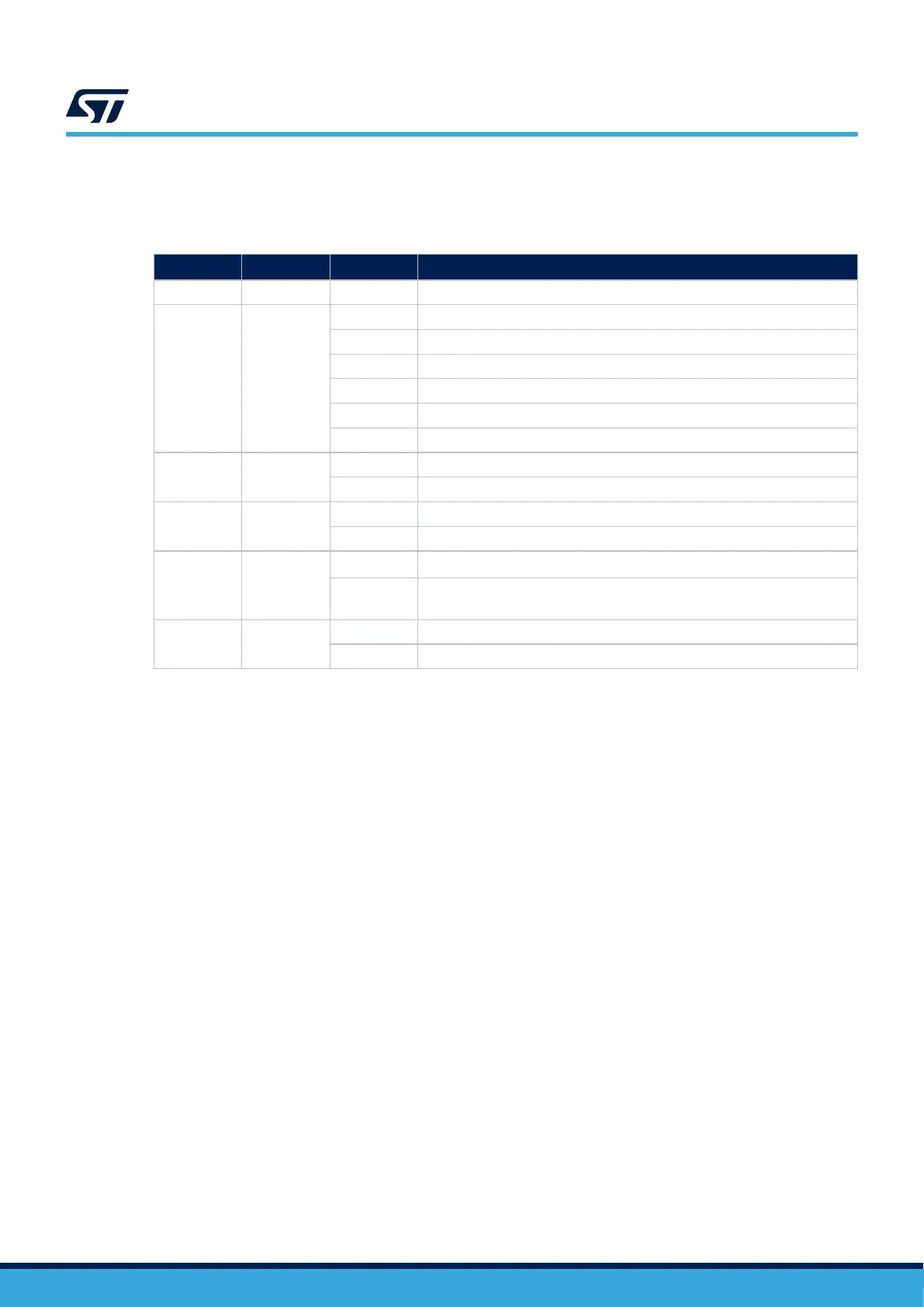
Table 10. Jumper configuration
Jumper/CN Function
State
(1)
Comment
JP1, JP2 GND ON GND probe
JP3
5 V power
selection
[1-2] 5 V from ST-LINK
[3-4] 5 V from E5V
[5-6] 5 V from user USB
[7-8] 5 V from VIN 7 V to 12 V
[9-10] 5 V from VBUS_STLK
OFF No 5 V power
JP4 STLK reset
OFF No STLK reset
ON STLK reset
JP5
NRST
connection
ON Reset signal from STLINK-V2EC to target MCU
OFF STLINK-V2EC cannot reset target MCU
JP6
Sensor power
selection
[1-2]
VDD is the temperature sensor and mikroBUS
™
connectors power supply
[2-3]
VDD_MCU is the temperature sensor and mikroBUS
™
connectors power
supply
JP7
IDD
measurement
ON VDD_MCU = VDD
OFF To connect the external source (ULPBench probe as an example)
1. The default jumper state is shown in bold.
UM3292
Hardware layout and configuration
UM3292 - Rev 1
page 17/33