7.2 Extension connectors (CN7 and CN10)
The extension connectors are two 2x20 2.54‑pitch male pin headers (CN7 and CN10). They can be used to
connect the STM32U083C-DK Discovery kit to an expansion or prototype/wrapping board placed on top of it. All
signals and power pins of the STM32 are available on the extension connectors. An oscilloscope, a logic
analyzer, or a voltmeter can also probe this connector.
Table 15 describes the CN7 and CN10 connector pinout.
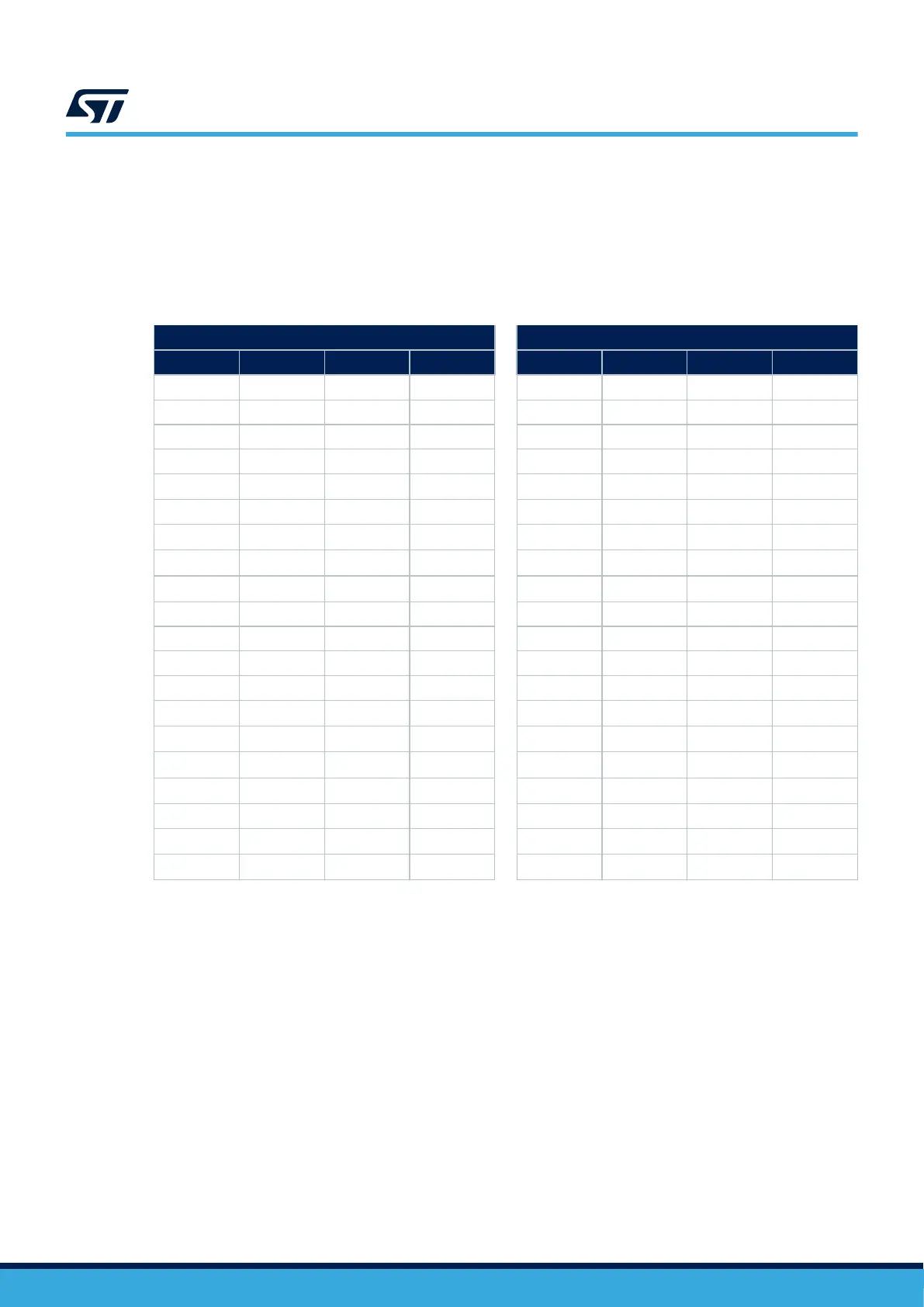
Table 15. Pin assignment for the STM32 on the extension connectors
CN7 CN10
Pin name Pin number Pin number Pin name Pin name Pin number Pin number Pin name
PD4 1 2 PD5 PD3 1 2 PA10
PC10 3 4 PC11 PC9 3 4 PC8
PB9 5 6 E5V PB8 5 6 PC6
VDDUSB 7 8 PD12 PB7 7 8 PC5
PF3-BOOT0 9 10 PD13 AVDD 9 10
VREF
(5)
PD6 11 12 PE7 AGND 11 12 PD8
PD9 13 14 VDD_MCU PA5 13 14
PA12
(3)
PA13
(1)
15 16 NRST PA6 15 16
PA11
(3)
PA14
(1)
17 18 VDD PA7 17 18
PB12
(4)
PA8 19 20 5V PA15 19 20 PB11
PD0 21 22 GND PC7 21 22 GND
PA9 23 24 GND PB6 23 24 PB2
PC13 25 26 PE8 PD2 25 26 PB1
PC14
(2)
27 28 PE9 PB10 27 28 PB15
PC15
(2)
29 30 PA0 PB4 29 30 PB14
PF0
(2)
31 32 PA1 PB5 31 32
PB13
(4)
PF1
(2)
33 34 PA4 PB3 33 34 PD1
VBAT 35 36 PB0 PC12 35 36 PC4
PC2 37 38 PC1 PA2 37 38
PD11
(4)
PC3 39 40 PC0 PA3 39 40
PD10
(4)
1. PA13 and PA14 are shared with SWD signals connected to STLINK-V2EC. It is not recommended to use them as I/O pins.
2. Refer to Section 6.5 for details.
3. Refer to Table 12 for details.
4. Refer to Table 13 for details.
5. The ADC input range is 0 <= VIN <= VREF.
UM3292
Connectors
UM3292 - Rev 1
page 23/33