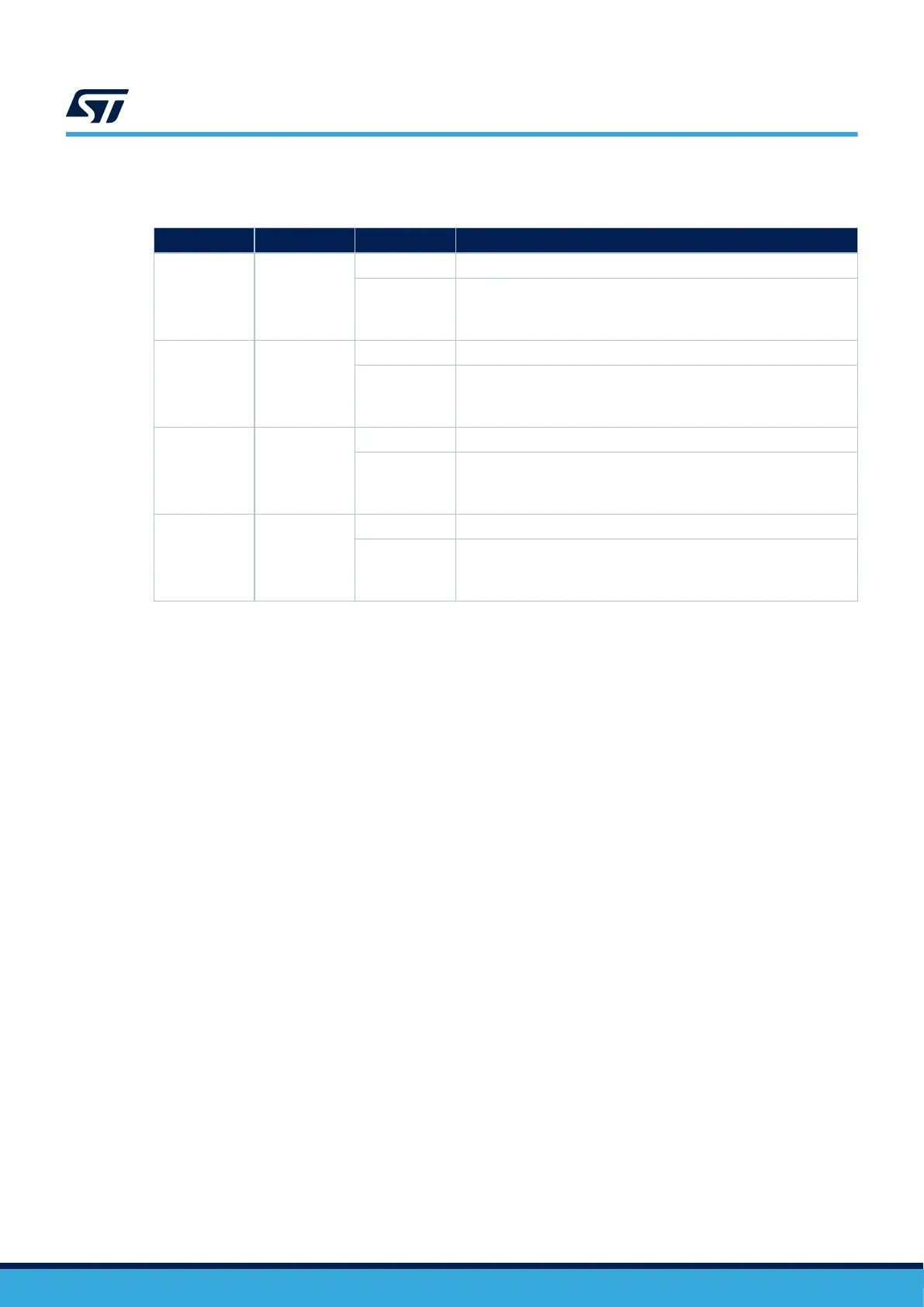
Table 13 describes the hardware configuration for the touchkey button interface.
Table 13. Hardware I/O configuration for the touchkey button interface
GPIO Hardware
Setting
(1)
Configuration
PD10 SB11
OFF PD10 is directly connected to TKEY_CS.
ON
PD10 can be used for extension I/O connectors. In this case, the touch
key layout is not optimized and the touchkey button may not be
functional.
PD11 SB9
OFF PD11 is directly connected to the touchkey button.
ON
PD11 can be used for extension I/O connectors. In this case, the touch
key layout is not optimized and the touchkey button may not be
functional.
PB12 SB23
OFF PB12 is directly connected to the SHIELD touchkey button.
ON
PB12 can be used for extension I/O connectors. In this case, the touch
key layout is not optimized and the touchkey button may not be
functional.
PB13 SB22
OFF PB13 is directly connected to SHIELD_CS.
ON
PB13 can be used for extension I/O connectors. In this case, the touch
key layout is not optimized and the touchkey button may not be
functional.
1. The default configuration is shown in bold.
6.14
Temperature sensor
The STM32U083C-DK Discovery kit embeds an ultra-low‑power temperature sensor with 0.5°C accuracy and
ALERT support. This sensor is managed with an I
2
C shared with the ARDUINO
®
and mikroBUS
™
connectors.
The I
2
C read/write address is 0x7F/0x7E.
The temperature sensor is powered by VDD or VDD_MCU by jumper JP6. Refer to Section 6.10 for jumper
configuration.
UM3292
Hardware layout and configuration
UM3292 - Rev 1
page 20/33