Hardware layout and configuration UM1902
18/79 DocID027916 Rev 2
connectors CN24 and CN27 can be used to support MEMS microphone evaluation board
STEVAL-MKI129V1 after removing SB20 and SB21.
An optical connector CN28, compatible with SPDIF spec, is implemented on STM32746G-
EVAL, to receive external audio data.
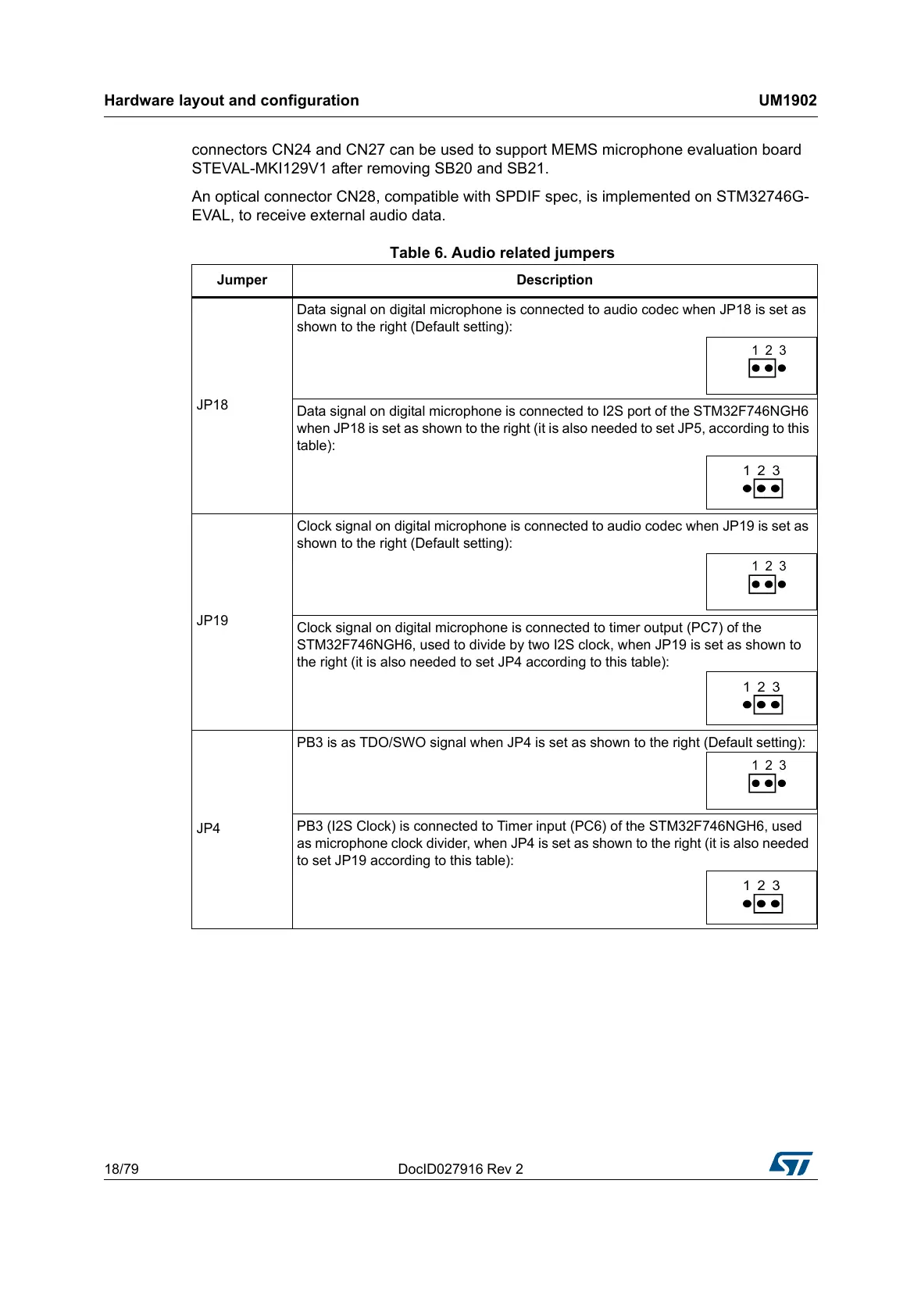
Table 6. Audio related jumpers
Jumper Description
JP18
Data signal on digital microphone is connected to audio codec when JP18 is set as
shown to the right (Default setting):
Data signal on digital microphone is connected to I2S port of the STM32F746NGH6
when JP18 is set as shown to the right (it is also needed to set JP5, according to this
table):
JP19
Clock signal on digital microphone is connected to audio codec when JP19 is set as
shown to the right (Default setting):
Clock signal on digital microphone is connected to timer output (PC7) of the
STM32F746NGH6, used to divide by two I2S clock, when JP19 is set as shown to
the right (it is also needed to set JP4 according to this table):
JP4
PB3 is as TDO/SWO signal when JP4 is set as shown to the right (Default setting):
PB3 (I2S Clock) is connected to Timer input (PC6) of the STM32F746NGH6, used
as microphone clock divider, when JP4 is set as shown to the right (it is also needed
to set JP19 according to this table):