DocID027916 Rev 2 45/79
UM1902 Connector
78
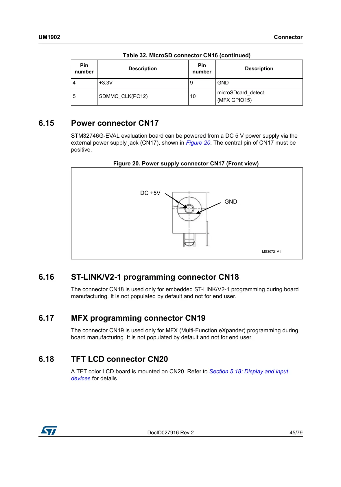
6.15 Power connector CN17
STM32746G-EVAL evaluation board can be powered from a DC 5 V power supply via the
external power supply jack (CN17), shown in Figure 20. The central pin of CN17 must be
positive.
Figure 20. Power supply connector CN17 (Front view)
6.16 ST-LINK/V2-1 programming connector CN18
The connector CN18 is used only for embedded ST-LINK/V2-1 programming during board
manufacturing. It is not populated by default and not for end user.
6.17 MFX programming connector CN19
The connector CN19 is used only for MFX (Multi-Function eXpander) programming during
board manufacturing. It is not populated by default and not for end user.
6.18 TFT LCD connector CN20
A TFT color LCD board is mounted on CN20. Refer to Section 5.18: Display and input
devices for details.
4 +3.3V 9 GND
5 SDMMC_CLK(PC12) 10
microSDcard_detect
(MFX GPIO15)
Table 32. MicroSD connector CN16 (continued)
Pin
number
Description
Pin
number
Description