DocID027916 Rev 2 25/79
UM1902 Hardware layout and configuration
78
5.18 Display and input devices
4-general-purpose-color leds (LD 1,2,3,4) are available for the display device and they are
connected on MFX.
The 4-direction joystick (B3) with selection, Wakeup/Tamper button (B2) are available as
input devices.
5.7-inch 640x480-pixel TFT color LCD with capacitive touch panel are connected to RGB
LCD interface of the STM32F746NGH6 microcontroller.
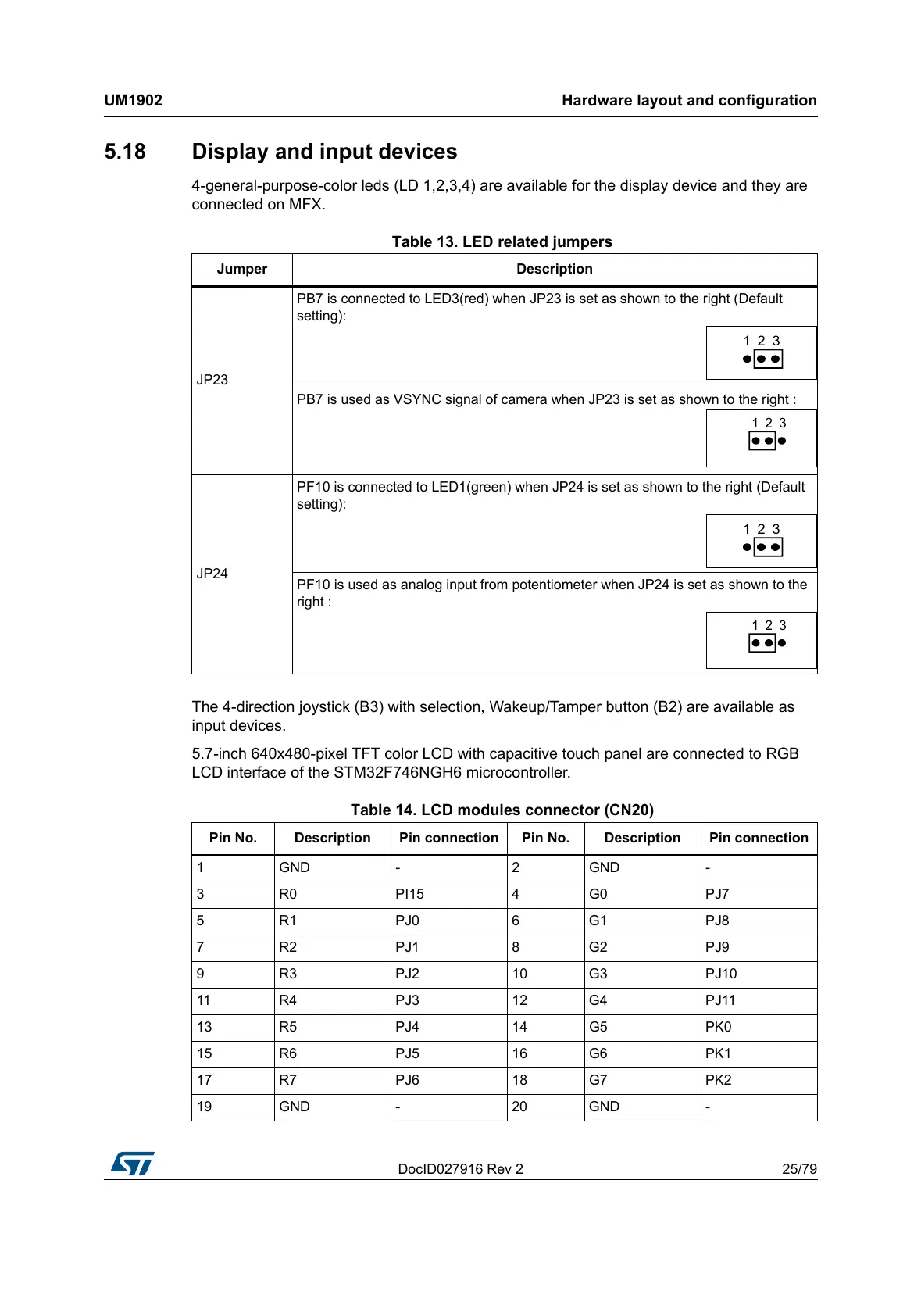
Table 13. LED related jumpers
Jumper Description
JP23
PB7 is connected to LED3(red) when JP23 is set as shown to the right (Default
setting):
PB7 is used as VSYNC signal of camera when JP23 is set as shown to the right :
JP24
PF10 is connected to LED1(green) when JP24 is set as shown to the right (Default
setting):
PF10 is used as analog input from potentiometer when JP24 is set as shown to the
right :
Table 14. LCD modules connector (CN20)
Pin No. Description Pin connection Pin No. Description Pin connection
1GND - 2GND -
3R0 PI15 4G0 PJ7
5 R1 PJ0 6 G1 PJ8
7 R2 PJ1 8 G2 PJ9
9R3 PJ2 10G3 PJ10
11 R4 PJ3 12 G4 PJ11
13 R5 PJ4 14 G5 PK0
15 R6 PJ5 16 G6 PK1
17 R7 PJ6 18 G7 PK2
19 GND - 20 GND -