Hardware layout and configuration UM1902
28/79 DocID027916 Rev 2
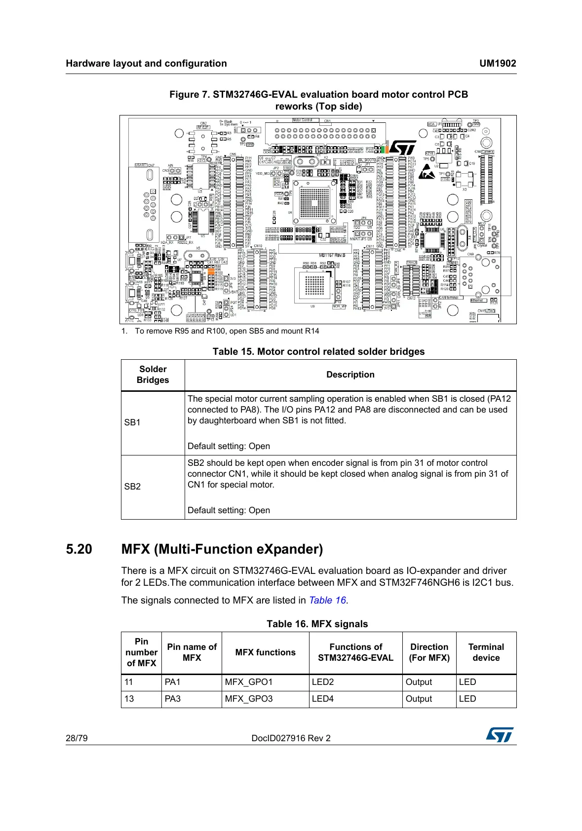
Figure 7. STM32746G-EVAL evaluation board motor control PCB
reworks (Top side)
1. To remove R95 and R100, open SB5 and mount R14
5.20 MFX (Multi-Function eXpander)
There is a MFX circuit on STM32746G-EVAL evaluation board as IO-expander and driver
for 2 LEDs.The communication interface between MFX and STM32F746NGH6 is I2C1 bus.
The signals connected to MFX are listed in Table 16.
Table 15. Motor control related solder bridges
Solder
Bridges
Description
SB1
The special motor current sampling operation is enabled when SB1 is closed (PA12
connected to PA8). The I/O pins PA12 and PA8 are disconnected and can be used
by daughterboard when SB1 is not fitted.
Default setting: Open
SB2
SB2 should be kept open when encoder signal is from pin 31 of motor control
connector CN1, while it should be kept closed when analog signal is from pin 31 of
CN1 for special motor.
Default setting: Open
Table 16. MFX signals
Pin
number
of MFX
Pin name of
MFX
MFX functions
Functions of
STM32746G-EVAL
Direction
(For MFX)
Terminal
device
11 PA1 MFX_GPO1 LED2 Output LED
13 PA3 MFX_GPO3 LED4 Output LED