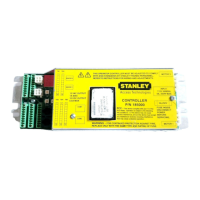
MC521 PRO Control Box
03.23.2017
1.800.7.ACCESS • www.stanleyaccess.com • Document # 204090 REV D 9
Copyright 2017 Stanley Access Technologies, LLC. All rights reserved. Reproduction
in whole or in part without the express written permission of Stanley is prohibited.
Wiring Swing Guard T
Caution: Do Not connect Swing Guard T Microboard or Sensors unl control box is fully tuned.
Note: Select Swing Guard T when in step 9 of Table 1 if tuning with pushbuons, even though
Swing Guard T has not been connected at this me. If tuning with ‘Hand held device’, select Swing Guard T
for Safety Logic in Step 6.
TB1 Terminal Connection Swing Guard T Wire Color
1 (+) Power for Swing Guard T Red
2 Serial Communicaon Green
3 Serial Communicaon White
4 (-) Power for Swing Guard T Black
Wiring Sensors
Note: Refer to Aachment 2, 3, 4, or 5 as applicable for wiring connecons
Wiring Bodyguard-T
Note: The Bodyguard-T does not require a lockout relay for use with the MC521 PRO control box. The MC521
PRO control box generates the data signals for door open, closing, and closed posions. Refer to Aachment 5 as
applicable for wiring connecons. Program the Bodyguard-T Relay Output to #1.
Wiring Superscan-T
Refer to Aachment 5 as applicable for wiring connecons. To inhibit the Stall Superscan-T, a switch is
required in series with the Stall output.
Wiring Holding Beam
The Holding Beam input is used in applicaons when there is a rail-mounted holding beam. When the door is
closing and the beam is obstructed, the door will not open unl the door is completely closed and the header-
mounted sensor becomes acve. When the door is open and the beam is obstructed, the door will remain open.
Refer to Aachment 5 as applicable for wiring connecons.