MC521 PRO Control Box
03.23.2017
1.800.7.ACCESS • www.stanleyaccess.com • Document # 204090 REV D 7
Copyright 2017 Stanley Access Technologies, LLC. All rights reserved. Reproduction
in whole or in part without the express written permission of Stanley is prohibited.
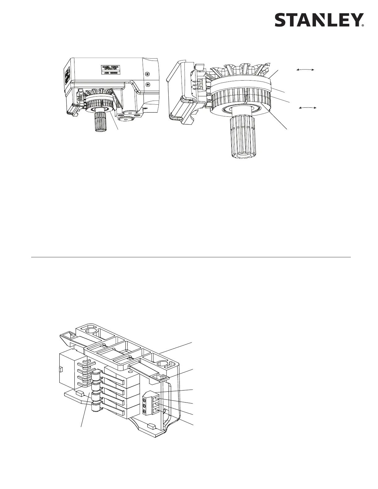
AUXILIARY CAM
CLOSE CHECK CAM
DECREASE
CLOSE CHECK
ANGLE
INCREASE
CLOSE CHECK
ANGLE
CAM ROTATION
BREAKOUT STATUS CAM
BREAKOUT CAM
DECREASE
BREAKOUT
ANGLE
INCREASE
BREAKOUT
ANGLE
CAM ROTATION
SEE DETAIL B
LEFT HAND OPERATOR
INITIAL CAM SETTINGS (LOOKING DOWN AT OPERATOR SPINDLE)
ROTATE BREAKOUT CAMS CLOCKWISE UNTIL RAISED PORTION OF BREAKOUT STATUS CAM JUST CONTACTS SWITCH ROLLER.
ROTATE CLOSE CHECK CAM COUNTERCLOCKWISE UNTIL RAISED PORTION OF CAM ACTUATES SWITCH, THEN ROTATE CAM 10 DEGREES CLOCKWISE.
ROTATE AUXILIARY CAM AS NEEDED
d. Using a mulmeter, CHECK connuity between TB3 terminals 9 and 10, and ENSURE there is connuity.
e. PUSH door in the breakout direcon, and HOLD door at approximately the negave 3-deg. posion.
f. Using a mulmeter, CHECK connuity between TB3 terminals 9 and 10, and ENSURE there is an open circuit.
g. RELEASE door.
h. PLUG TB3 into control box.
Wiring the Operator Switch Module (Magic-Force Operators)
• Refer to Aachment 2 or 3 as applicable, and CONNECT switch module harness 413791 to dual-adjustment
closing speed control connector J4.
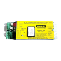
• IF auxiliary posion switch will be used, refer to Figure 3, and PERFORM the following:
a. LIFT switch module release lever up, and SLIDE switch module out of operator housing.
b. CONNECT wiring to auxiliary posion switch terminal block as shown.
c. SLIDE switch module into operator housing unl switch module release lever snaps into place.
SWITCH MODULE
SWITCH MODULE RELEASE LEVER
(PRESS LEVER UP TO RELEASE SWITCH MODULE)
AUXILIARY POSITION SWITCH
TERMINAL BLOCK
NORMALLY CLOSED CONTACT
COMMON
NORMALLY OPEN CONTACT
OPERATOR HOUSING
Figure 3. Wiring the Auxiliary Position Switch (Magic-Force Operators)
Figure 2. Continued.
Breakout Status/Breakout Cam Settings - Magic Force Operators