MC521 PRO Control Box
6 Document # 204090 REV D • www.stanleyaccess.com • 1.800.7.ACCESS
Copyright 2017, Stanley Access Technologies, LLC. All rights reserved. Reproduction
in whole or in part without the express written permission of Stanley is prohibited.
03.23.2017
Connecting Breakout Status Signal Wiring (Magic-Force Operators)
Warning: To prevent injury to personnel and damage to equipment, control box power must be deenergized
before connecng breakout status signal wiring.
Caution: If the motor is running and the breakout status switch is not connected, arcing across the breakout
switch contacts can occur. This will result in damage to the breakout switch. To prevent damage from switch
contact arcing, the breakout status switch must always be connected.
• SET “POWER” switch to OFF.
• IF single-operator applicaon, PERFORM the following:
a. INSTALL one breakout status switch wire to terminal 9 of control box connector TB3.
b. INSTALL second breakout status switch wire to terminal 10 of control box connector TB3.
• IF dual-operator applicaon, PERFORM the following to put the breakout switches in series:
a. INSTALL one breakout status switch wire from one operator to terminal 9 of control box connector TB3.
b. INSTALL one breakout status switch wire from second operator to terminal 10 of control box connector TB3.
c. CONNECT remaining two yellow breakout status switch wires together with a wire nut.
• VERIFY breakout status/breakout cams are properly set as follows:
a. Refer to Figure 2, and visually INSPECT cams for proper seng.
b. UNPLUG TB3 from control box.
NOTE: When checking breakout status switch connuity, the switch is checked twice; rst with the
door closed, then with the door in the breakout (negave 3°) posion. In a dual-door applicaon, both
doors can be tested at the same me in the closed posion. However, the doors must be tested
individually when checking switch connuity with the doors in the breakout (negave 3°) posion.
c. ENSURE door is in the closed posion.
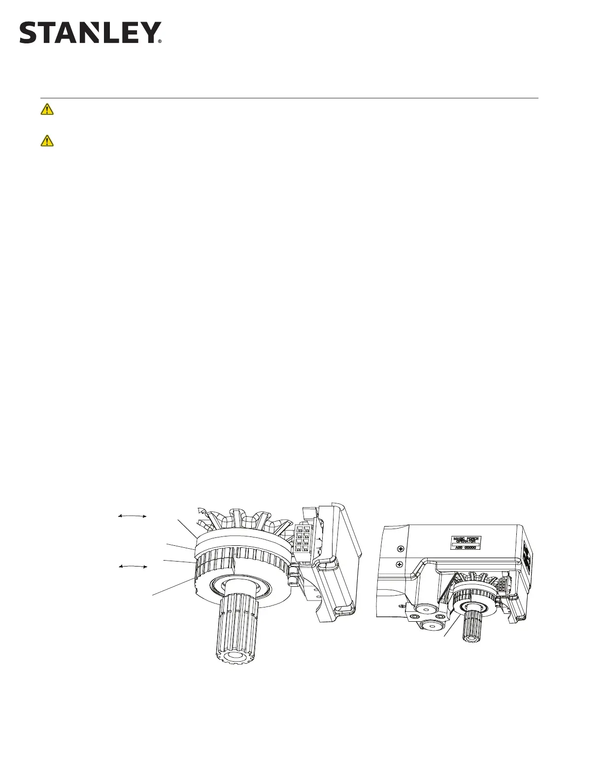
Figure 2. Breakout Status/Breakout Cam Settings - Magic Force Operators
(Continued next page).
BREAKOUT CAM
BREAKOUT STATUS CAM
CLOSE CHECK CAM
AUXILIARY CAM
INCREASE
BREAKOUT
ANGLE
DECREASE
BREAKOUT
ANGLE
CAM ROTATION
INCREASE
CLOSE CHECK
ANGLE
DECREASE
CLOSE CHECK
ANGLE
CAM ROTATION
SEE DETAIL A
RIGHT HAND OPERATOR
INITIAL CAM SETTINGS (LOOKING DOWN AT OPERATOR SPINDLE)
ROTATE BREAOUT CAMS COUNTER-CLOCWISE UNTIL RAISED PORTION OF BREAOUT STATUS CAM JUST CONTACTS SWITCH ROLLER.
ROTATE CLOSE CHECK CAM CLOCWISE UNTIL RAISED PORTION OF CAM ACTUATES SWITCH, THEN ROTATE CAM 10 EGREES COUNTER-CLOCWISE.
ROTATE AUILIARY CAM AS DESIRED.