MC521 PRO Control Box
03.23.2017
1.800.7.ACCESS • www.stanleyaccess.com • Document # 204090 REV D 5
Copyright 2017 Stanley Access Technologies, LLC. All rights reserved. Reproduction
in whole or in part without the express written permission of Stanley is prohibited.
• Repeat for second door operator: CONNECT yellow jumper wires installed on the single/dual motor harness as
follows:
a. INSTALL stripped end of rst jumper wire (from posion 3 of the 8-pin connector on operator harness) into
terminal 9 of control box connector TB3.
b. INSTALL stripped end of second jumper wire (from posion 5 of the 8-pin connector on operator harness)
into terminal 10 of control box connector TB3.
• Repeat for second door operator: SET the auxiliary cam for approximately 3° acvaon (toward breakout direc-
on), and ADJUST cam as necessary to trip the corresponding microswitch prior to acvaon of the breakout
switch.
Note: In a dual-door applicaon, the breakout switches of each operator need to be wired in series to ensure
that the control box will not open the doors if either breakout status switch is acvated.
• IF applicaon is a pair of doors, PERFORM the following:
a. REPEAT the previous two steps for the second door operator.
b. CONNECT stripped end of one yellow jumper wire from each operator to terminals 9 and 10 of control box
connector TB3.
• Using a wire nut, CONNECT remaining wire from rst operator to remaining wire on second operator.
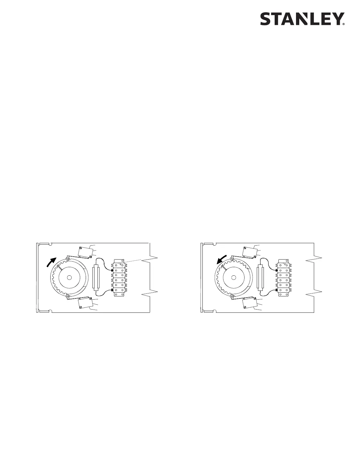
• VERIFY breakout status/breakout cam is properly set as follows:
a. Refer to Figure I, and visually INSPECT cams for proper seng.
b. UNPLUG TB3 from control box.
Note: When checking breakout status switch connuity, the switch is rst checked with the door closed,
then again with the door in the breakout (negave 3°) posion. In a dual-door applicaon, both doors can
be tested at the same me in the closed posion. However, the doors must be tested individually when
checking switch connuity with the doors in the breakout (negave 3°) posion.
c. ENSURE door is in the closed posion.
d. Using a mulmeter, CHECK connuity between TB3 terminals 9 and 10, and ENSURE there is connuity.
e. PUSH door in the breakout direcon, and HOLD door at approximately the negave 3° posion.
f. Using a mulmeter, CHECK connuity between TB3 terminals 9 and 10, and ENSURE there is an open circuit.
g. RELEASE door.
h. PLUG TB3 into control box.
TOP CAM = AUX SWITCH
CENTER CAM = EMERGENCY BREAKOUT SWITCH
BOTTOM CAM = CLOSE CHECK SWITCH
EMERGENCY SWITCH
N.C.: RED
N.O.: YELLOW
COM.: BLACK
OPEN CHECK SWITCH
N.O.: BROWN
COM.: ORANGE
CLOSE CHECK SWITCH
N.C.: WHITE
COM.: BLUE
TOP CAM = AUX SWITCH
CENTER CAM = EMERGENCY BREAKOUT SWITCH
BOTTOM CAM = CLOSE CHECK SWITCH
RH SHOWN RH SHOWN
Figure 1. Breakout Status/Breakout Cam Settings (Magic-Swing Operators)
N.O.
N.C.
COM
N.O.
N.C.
N.C.
COM
N.O.
N.C.
N.O.