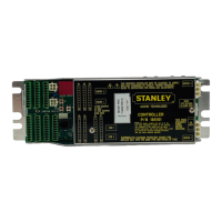
MC521 PRO Control Box
4 Document # 204090 REV D • www.stanleyaccess.com • 1.800.7.ACCESS
Copyright 2017, Stanley Access Technologies, LLC. All rights reserved. Reproduction
in whole or in part without the express written permission of Stanley is prohibited.
03.23.2017
WIRING INSTRUCTIONS
Evaluate Power Requirements
EVALUATE door system power requirements as follows:
• ENSURE power source is a dedicated 115 VAC, 50/60 Hz source with 20A circuit rang per two controllers.
• ENSURE power source is not shared with other equipment, i.e., cash registers, EAS systems, or other
electromagnetic interference generators.
Connecting Main Power Wiring
Warning: To prevent injury to personnel, incoming electrical power to header must be deenergized before
connecng control box electrical harness to electrical service.
• DEENERGIZE incoming electrical power to header.
• Refer to Aachments 2, 3, and 4, and using the wire nut provided, CONNECT ground wire assembly (P/N
711527) to electrical service ground wire.
• In a concealed locaon inside the header (not visible from the exterior of the header), DRILL a hole for a
No. 8 screw.
• INSTALL ground wire ring terminal and star washer onto the No. 8 screw provided, and FASTEN screw, star
washer, and ground wire to header.
• In a concealed locaon inside the header, DRILL a second hole for a No. 8 screw.
• INSTALL power line harness 412544 ring terminal and star washer onto the No. 8 screw provided, and
FASTEN screw, star washer, and ground wire to header.
• Using the wire nuts provided, CONNECT power line harness 412544 to electrical service as follows:
• CONNECT power pigtail assembly black wire to black (line) service wire.
• CONNECT power pigtail assembly white wire to white (neutral) service wire.
Connecting Breakout Status Signal Wiring (Magic-Swing Operators)
Warning: To prevent injury to personnel and damage to equipment, control box power must be deenergized
before connecng breakout status signal wiring.
Caution: If the motor is running and the breakout status switch is not connected, arcing across the breakout
switch contacts can occur. This will result in damage to the breakout switch. To prevent damage from switch
contact arcing, the breakout status switch must always be connected.
Notes:
The breakout status switch should be used in all applicaons where there is no posive door stop in the
breakout direcon.
The auxiliary switch is the breakout status signal switch. The auxiliary switch was formerly the open check
switch on the operator switch plate (top cam).
• Refer to Aachment I, and CONNECT breakout status wiring.
• REMOVE quick-connect terminal (brown wire) from the normally open terminal of the auxiliary
switch (formerly open check switch), and INSTALL onto normally closed terminal.
2

 Loading...