PARTS REPLACEMENT
– 44 –
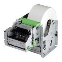
3. Printer Mechanism
(1) Remove
• Upper case unit according to the procedure de-
scribed in item 1.
• Stop ring [1]
• Release cam [2]
• Release gear [3]
• Four screws [4]
• Screws [5]
• Connector cover [6]
Holding up the tab of the connector cover, slide
the connector cover to the right for removal.
• Head cable [7]
• Three connectors [8]
• Printer mechanism [9]
Lean the printer mechanism [9] to prevent inter-
ference with the release shaft [10].
Caution in assembly:
Of the two ∆ marks on the release cam [2] , one
must align with the same mark on the release gear
[3] , and the other must align with the same mark
on the release lever [11].
4. Main Logic Board
(1) Remove
• Printer mechanism according to the procedure
described in item 3.
• Two connectors [1]
• Three tapping screws [2]
• Main logic board [3]
Undo the four hooks [4] fastening the main logic
board.
 Loading...