Do you have a question about the Star Micronics NX-1000 series and is the answer not in the manual?
Introduces the printer models covered and the manual's section breakdown.
Details the printing, paper, and interface specifications for parallel type printers.
Details printing, character sets, and interface specs for Commodore type printers.
Covers printer physical dimensions, weight, power, environment, print head, and ribbon.
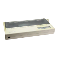
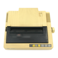
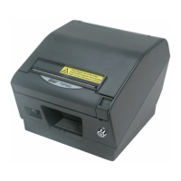
Describes the printer's external parts and internal composition diagrams.
Explains the function of DIP switches for parallel and Commodore type printers.
Details pin assignments and functional descriptions for parallel and Commodore interfaces.
Explains the printer's block diagram and the functions of its main logic board components.
Details the data input and handshake procedures for parallel and Commodore interfaces.
Provides a flowchart illustrating the printer's editing and printing operations.
Describes the drive circuits and control signals for carriage and paper feed motors.
Explains reset mechanisms, protection circuitry, and the power supply unit.
Details the operational mechanisms of the print head, carriage, ribbon feed, paper feed, and detectors.
Provides procedures for measuring and adjusting the gap between the print head and the platen.
Details the method for adjusting the timing belt tension to the specified value.
Explains adjustments for home position detector and colour ribbon holder.
Instructions for removing and replacing the printer's upper case and main mechanism.
Procedures for replacing logic board, power supply unit, and fuses.
Steps for replacing print head, motors, platen, tractor, and detector units.
Procedures for cleaning the printer and performing daily and periodic checks.
Details recommended lubricants and the process for lubricating printer parts.
Illustrates the specific areas within the printer that require lubrication.
Outlines initial repair steps and a flowchart for unit replacement based on problems.
Detailed flowcharts and guidance for troubleshooting by replacing major units.
Flowcharts for diagnosing and repairing issues by replacing specific components.
Comprehensive lists of parts for printer assembly and mechanism.
Parts lists for sub-assemblies, wiring schemes, and logic boards.
Details power supply unit parts, circuit diagrams, and oscilloscope waveform examples.
Lists parts for the printer assembly and mechanism specific to Version 2.
Parts lists for sub-assemblies, wiring schemes, and logic boards for Version 2.
Details parts for the Version 2 power supply unit and provides waveform information.
Explains the function and pin assignments of key ICs like CPU, Gate Array, ROM, and RAM.
Details the operation and characteristics of transistor arrays and voltage detecting ICs.
Provides diagrams and explanations for specific transistor components used in the printer.
| Brand | Star Micronics |
|---|---|
| Model | NX-1000 series |
| Category | Printer |
| Language | English |