PARTS REPLACEMENT
– 47 –
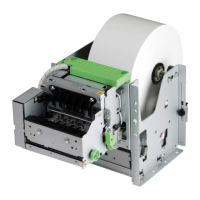
9. Platen Unit
(1) Remove
• Upper case unit according to the procedure de-
scribed in item 1.
• Paper feed roller unit [1]
• Stop ring [2]
• Gear [3]
• Two nuts [4]
• Tractor stay [5]
• Stop ring [6]
• Ground contact spring [7]
• Two platen holders [8]
Holding up the tab [9] of the platen holder [8] ,
turn the platen holder for removal from the frame.
• Platen unit [10]
Slide the platen unit [10] to the right until the
shaft comes off from the platen gear assembly
[11] and then lift the platen unit.
Caution in assembly:
When the platen gear assembly [11] meshes with
the idler gear, align the teeth of gear A and gear B
(be sure to align the holes [12] in the two gears).
(2) Adjust
• Gap between print head and platen
Refer to item 1 of Chapter 3.
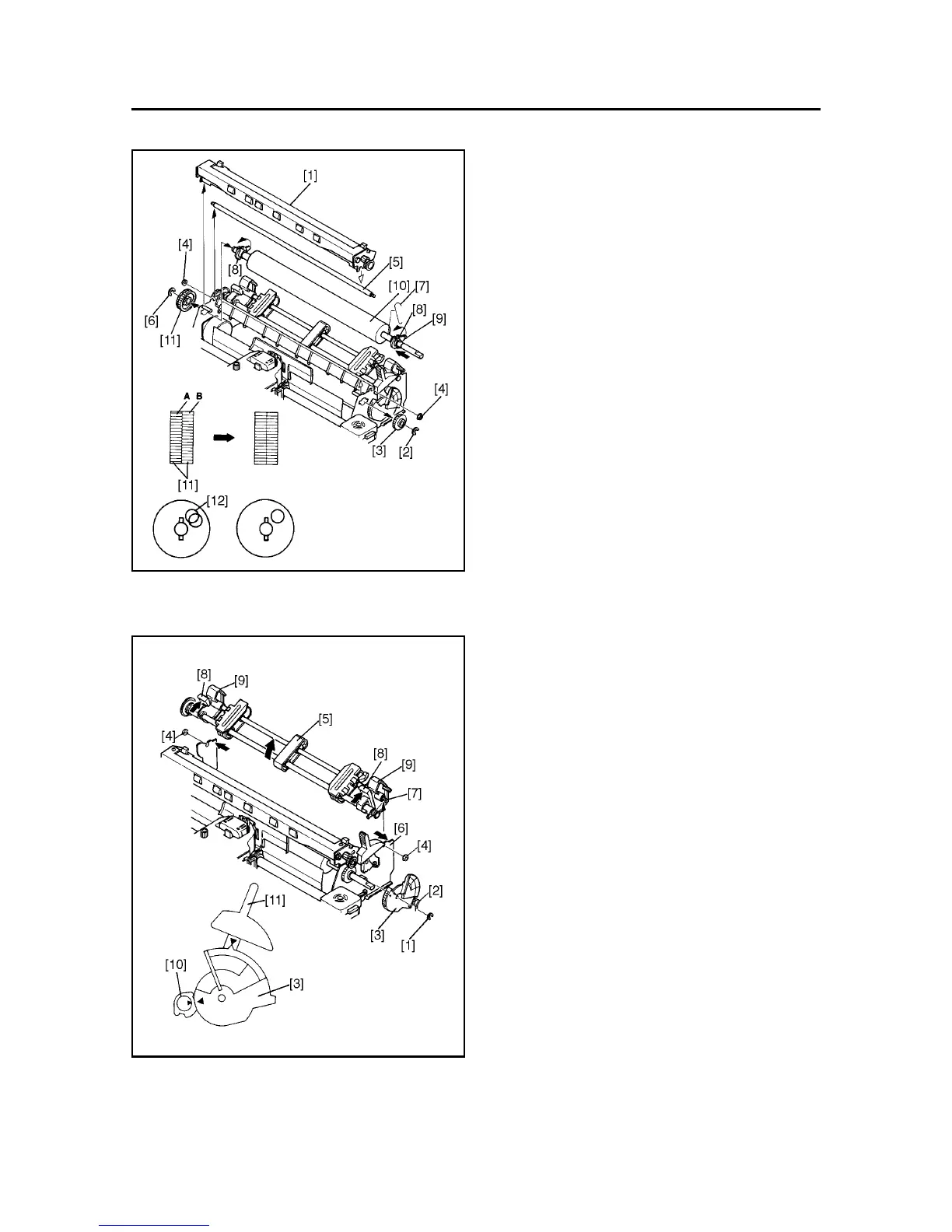
10. Tractor Unit
(1) Remove
• Upper case unit according to the procedure de-
scribed in item 1.
• Stop ring [1]
• Release lever spring [2]
• Release cam [3]
• Two nuts [4]
• Tractor unit [5]
With the frames [6] open and the tractor stay [7]
released, pinch the two levers [8] and turn the two
tractor sub-units [9] .
Caution in assembly:
Of the two ∆ marks on the release cam [3] , one
must align with the same mark on the release gear
[10] , and the other must align with the same mark
on the release lever [11].
 Loading...