Do you have a question about the Staubli TX Series and is the answer not in the manual?
General introduction to the manual, copyright, disclaimers, and contact information.
Defines key terminology such as Person, Staff, User, and Operator within the robot cell environment.
Covers safety standards, work environment directives, staff protection, and equipment protection.
Explains how to identify the robot using the manufacturer's plates on the controller and arm.
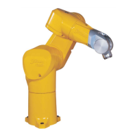
Provides an overview of the robot arm's structure, joint movements, servomotors, and key components.
Explains the naming convention for TX Series 40 family robots, including family, radius, joints, and options.
Details dimensions, work environment specifications (temp, humidity, altitude), and weight of the robot arm.
Details amplitude, speed, and resolution for each axis, as well as work envelope and repeatability.
Covers load capacity, torque limits, and attachment of additional loads on the robot arm's mechanical interface.
Details the arm cabling system, electrical and pneumatic connections for rear and vertical cable outlets.
Explains standard and optional pneumatic systems (compressed air, vacuum) and the electric circuit.
Defines requirements for the robot's installation and working space, including safety enclosures and access.
Details the mounting requirements for the robot arm, including surface flatness and attachment points.
Provides specifications for standard and international packaging, including dimensions and gross weight.
Briefly mentions handling of the packaging using a pallet truck.
Outlines the steps for moving, opening the case, and removing packing wedges and bolts.
Details positioning, attachment, mounting floor quality, and amplitude modification during arm installation.
Categorizes maintenance tasks into three levels based on required training and expertise for safe intervention.
Provides step-by-step instructions for removing and fitting new seals on the robot arm covers.
Specifies routine annual checks and recommended maintenance after 20,000 hours of operation.
Details software joint positions and observed oil levels for checking when the arm is floor-mounted or ceiling-mounted.
Lists essential spare parts, including oils and seal kits, and cautions about using original parts.
| Type | Industrial Robot |
|---|---|
| Degrees of Freedom | 6 |
| Model | TX Series |
| Category | Robotics |
| Protection Class | IP54 or IP67 (depending on model) |
| Controller | CS8, CS9 |
| Mounting | Floor, Wall, Ceiling |