Chapter 5 – Preventive maintenance
D28065504A - 02/2007 79
5.4.2. ARM IN CEILING-MOUNTED POSITION (figure 5.2)
5.4.2.1. SOFTWARE ANGULAR POSITION OF JOINTS FOR CHECKING LEVELS.
5.4.2.2. LEVELS TO BE OBSERVED
With the robot in position specified above, the oil levels to be observed are as follows:
• Joint 1:
• Remove the arm from its support by proceeding in the reverse order to installation.
• Place the arm in position on the floor.
• Follow the arm on floor procedure.
• Joint 2: The oil level coincides with the base of hole after removing cap (1).
• Joint 3: The oil level coincides with the base of hole after removing cap (2).
• Joint 4: The oil level coincides with the base of hole after removing cap (3).
• Joints 5 and 6: The oil should be flush with the bottom of the holes after the plugs (4) have been removed.
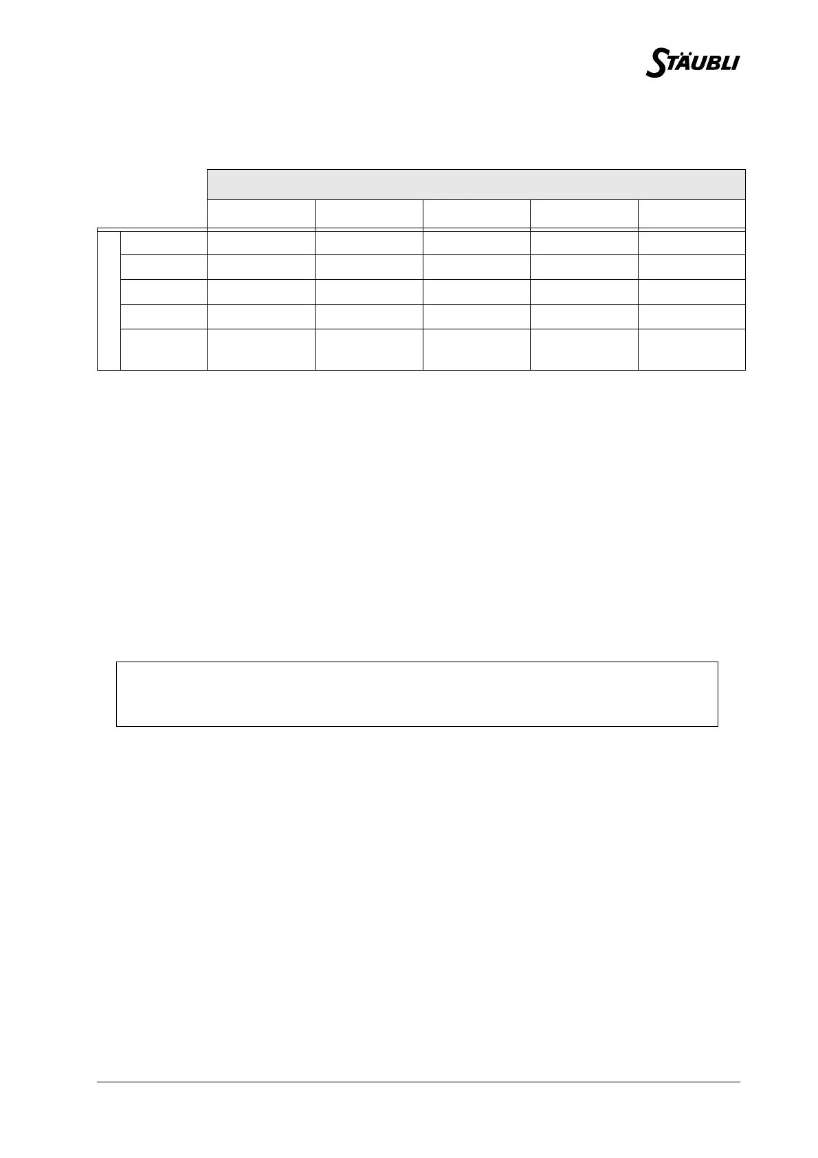
Position
Joint 1 Joint 2 Joint 3 Joint 4 Joint 5
Check
Joint 10°0°0°0°0°
Joint 20°0°0°0°0°
Joint 30° 105° -90° 0° 0°
Joint 40° 105° -90° 0° 0°
Joints 5
and 6
0° 105° -90° 0° 0°
CAUTION:
Too much or too little oil can prevent the robot from operating correctly.