Chapter 2 – Description
D28065504A - 02/2007 31
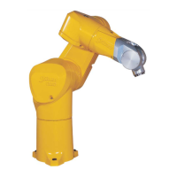
2.6. LOAD CAPACITY – MECHANICAL INTERFACE
See figure 2.6.
Terminal (2) is not supplied with the arm assembly; its design depends on the robot’s specific applications.
All studies can be undertaken in cooperation with STÄUBLI to obtain optimum performance without
exceeding the robot arm assembly load limits.
Terminal (2) is mounted on the wrist's mechanical interface (1) (dimensions given in Figure 2.6).
Secured by 4 class 12-9 screws M5 (4), tightening torque 9.5 Nm ± 0.7 Nm.
Indexing pin, 5-mm diameter pin (3).
Mechanical interface designation:
ISO 9409 - 1 - A31.5 as per Standard ISO 9409 - 1 : 1996 (F)
(except the localization of the 4 M5 threaded holes)
CAUTION:
Length of end-effector attaching screws is limited to avoid all interference with the wrist
(figure 2.6).