CL42T(V4.1) Closed-Loop Stepper Driver
8
6.
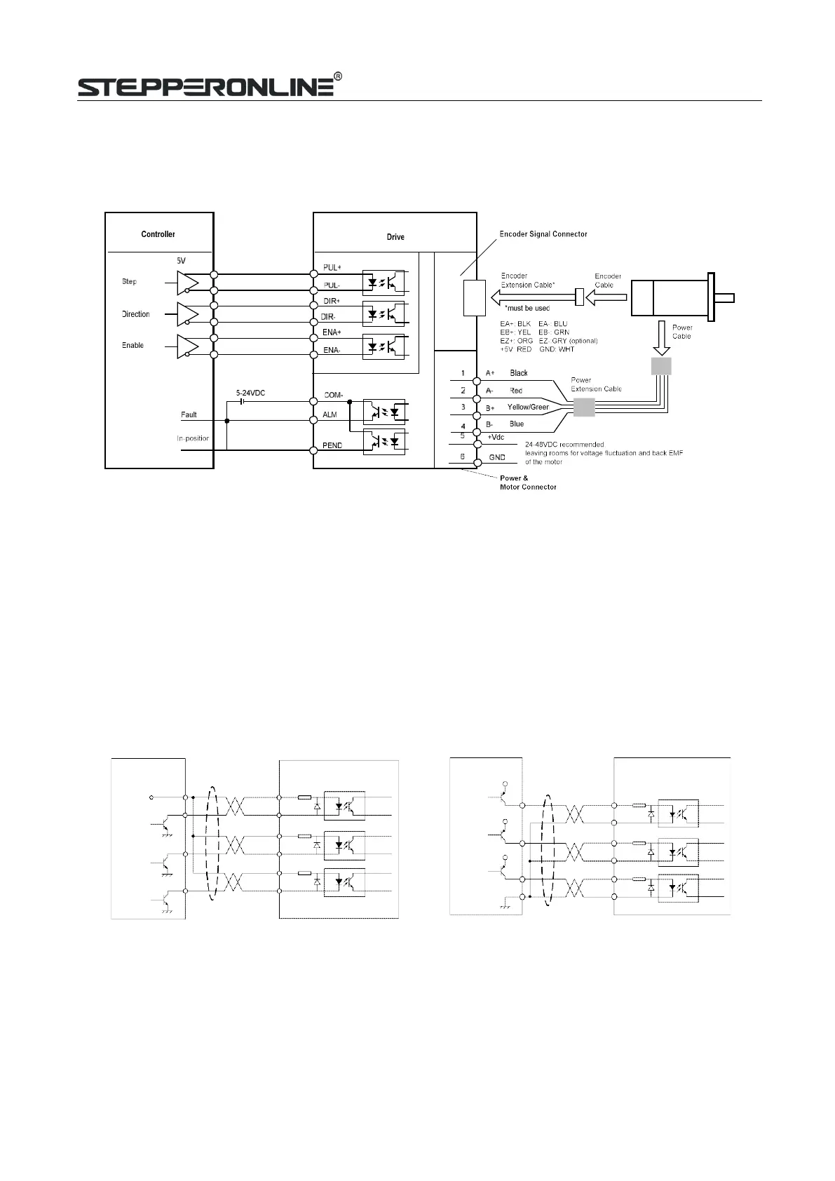
Typical Connection
A complete closed loop stepper system should include a stepper motor with encoder, CL42T(V4.1) drive,
powersupply and controller (pulse generator). A typical connection is as below.
Notes:
Figure 4: Typical connection
(1)
Pulse and direction inputs level 5V or 24V selected by selector switch S3. When it is 24 V, the S3
selection of 5V will damage the input photo-coupling.
(2)
Enable (ENA) signal is 5V~24V compatible.
6.1
Digital Input Connection
The CL42T(V4.1) can accept can accept differential or single-ended control signals (pulse, direction, and
enable) in open-collector or PNP connection through the P1 connector (figure 2). It is recommend to add
an EMI line filter between the power supply and the drive to increase noise immunity for the drive in
interference environments.
DIR-
ENA-
DIR-
Figure 5: Connections to open-collector signal Figure 6: Connections to PNP
signal (common-anode) (common-cathode)