CL42T(V4.1) Closed-Loop Stepper Driver
6
Higher supply voltage can increase motor torque at higher speeds (>300 RPM), thus helpful for avoiding losing
steps.However, higher voltage may cause bigger motor vibration at lower speed, and it may also cause over-
voltage protection or even drive damage.
5.
Switch Configurations
5.1
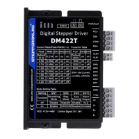
S1 - Rotating Switch Configurations
This rotating switch is used to set the peak current of the drive and motion gain, from the motor phase
current andapplication requirements.
Peak
Current
RMS
Current
Code
Velocity
loop Ki
loop Kp
Velocity
loop Kp
Remark
0.8 0.6
0 (factory)
0 25 25
1)
Velocity loop Ki Indicates the stop
time and position accuracy, “0”
indicates the stop time is long, but the
position error issmaller.“16” means
the stop time is short,but the position
error is slightly larger.
2)
Position loop Kp and velocity loop Kp
is a pair of composite parameters that
representrigidity. “25” and “25”composite
parametersindicate the rigidity is weak,
“100” and “5”composite parameters
indicate the rigidity is strong. Sometimes
if the motor
will rotate after stopping, it can increase
thevalue of position loop Kp, but if the
value is too large, the motor will have
noise.
3)
Usually keep factory settings
1
0 50 15
2
16 25 25
3
16 50 15
1.4 1
4
0 25 25
5
0 50 15
6
16 25 25
7
16 50 15
2.1 1.5
8
0 25 25
9
0 50 15
A
16 25 25
B
16 50 15
2.8 2
C
0 25 25
D
0 50 15
E
16 25 25
F
16 50 15
5.2
S2 - DIP Switch Configurations
The 8-bit is located on the side (DIP switch S2 in Figure 2) and used to configure settings of micro step
resolution,output current, and motor standstill current as shown below
SW1 SW2 SW3 SW4 SW5
SW6
SW7 SW8
Microstep
Rotation
Pulse mode
Pulse filter time
Control mode
Figure 3: DIP switches