CL42T(V4.1) Closed-Loop Stepper Driver
3
3.
Connections and LED Indication
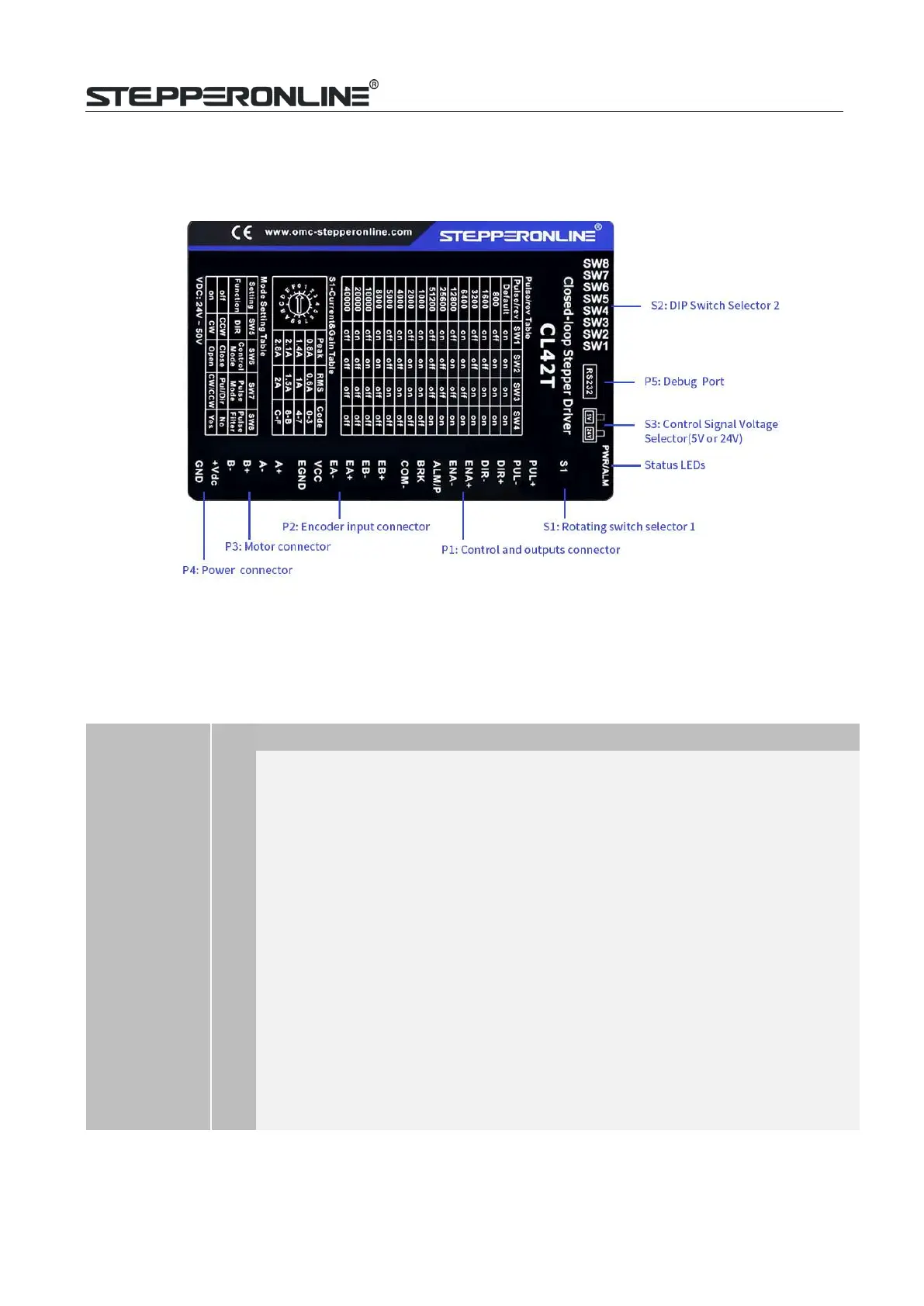
A CL42T(V4.1) closed loop stepper drive has 5 connection blocks from P1 to P5 (see figure 2).
Figure 2: CL42T(V4.1) connectors
3.1
P1 – Control and Digital Output Connections
The P1 connector in Figure 2 contains connections for control signals and 2 digital outputs.See the following
table for details.
PIN
I/O
Details
PUL+
(CW+)
I
Pulse and Direction Connection:
(1)
Optically isolated, high level 3.5-5V or 24V, low voltage 0-0.5V
(2)
Maximum 500 KHz input frequency
(3)
The width of PUL signal is at least 1.0μs, duty cycle is recommended 50%
(4)
Single pulse (step & direction) or double pulse (CW/CCW) is set by DIP Switch
SW7
(5)
DIR signal requires advance PUL signal minimum 2 μs in single pulse mode
(6)
The factory setting of control signal voltage is 24V, must need to set S3 (figure
2) if it is 5V
PUL- (CW-)
I
DIR+
(CCW+)
I
DIR- (CCW-)
I
ENA+
I
Enable Signals: Optional.
(1)
Effective high level is 3.5-24V; Effective low level is 0-0.5V connection
(2)
ENA signal requires advance DIR signal minimum 200ms in single pulse mode,
(default no connection)
ENA-
I
ALM O
Alarm: They takes a sinking or sourcing 100mA current at 5-24V. Max 30VBrake:
Max. 24/100mA, connect with brake coil, relay and diode.
Common connection of single-end output signals (common-cathode)
BRK O
COMO
O