CL42T(V4.1) Closed-Loop Stepper Driver
9
Notes:
(1)
ENA signal is no-connected as default;
(2)
Control signal amplitude is 24 V as default. If it is 12 V, please set the S3 (Figure 2) selector switch to 5 V
first, then connect 1KΩ resistor; If it is 5V, please set the S3 to 5V.
6.2
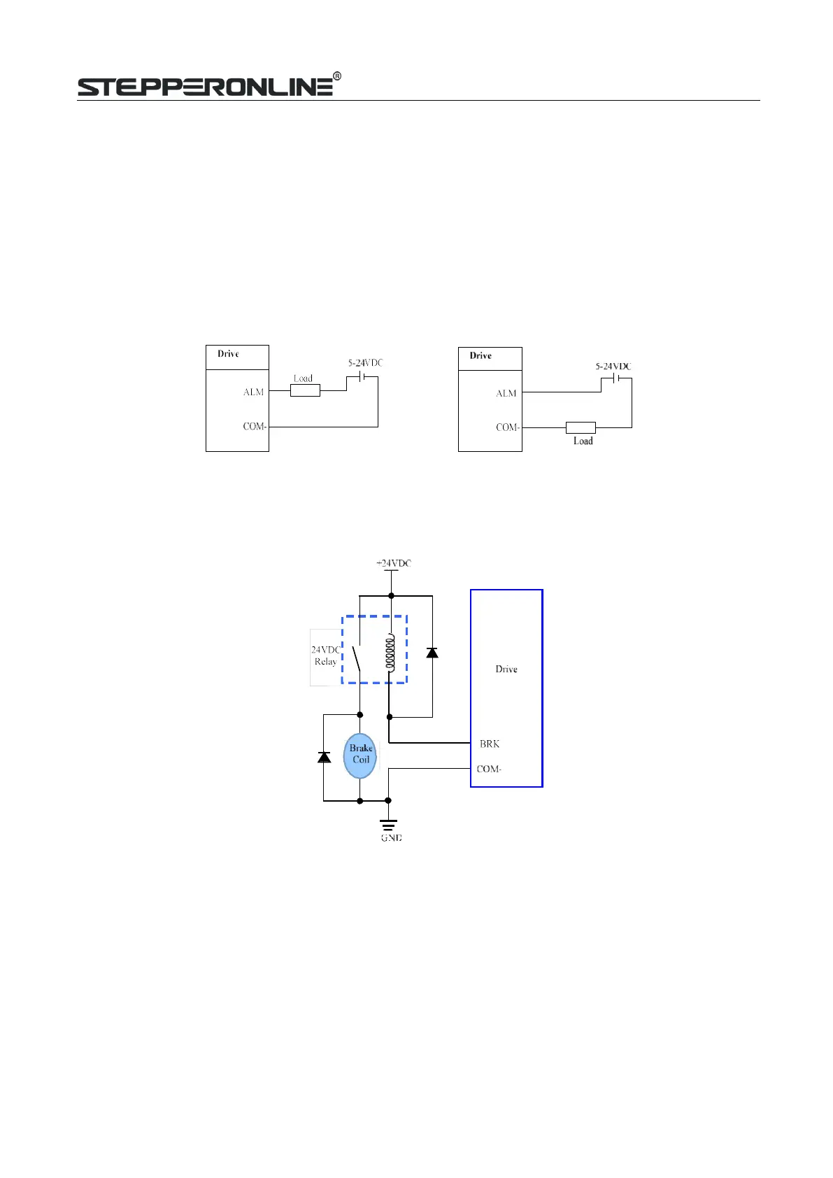
Fault Output Connection
When over voltage or over current protection happens, CL42T(V4.1) red status LED light will blink and the
impedancestate between ALM and COM- will change (from low to high or high to low depending on
configuration) and can thusbe detected. Fault output connection is optional, and it can be connected either in
sinking or sourcing.
Figure 7 Sinking output Figure 8 Sourcing output
6.3
Brake Output Connection
This drive has a special brake output, it needs to drive the motor brake with a relay. The connection is below:
Figure 9 Brake output connection
7.
Sequence Chart of Control Signals
In order to avoid some fault operations and deviations, PUL, DIR and ENA should abide by some rules, shown
asfollowing diagram: