CL42T(V4.1) Closed-Loop Stepper Driver
10
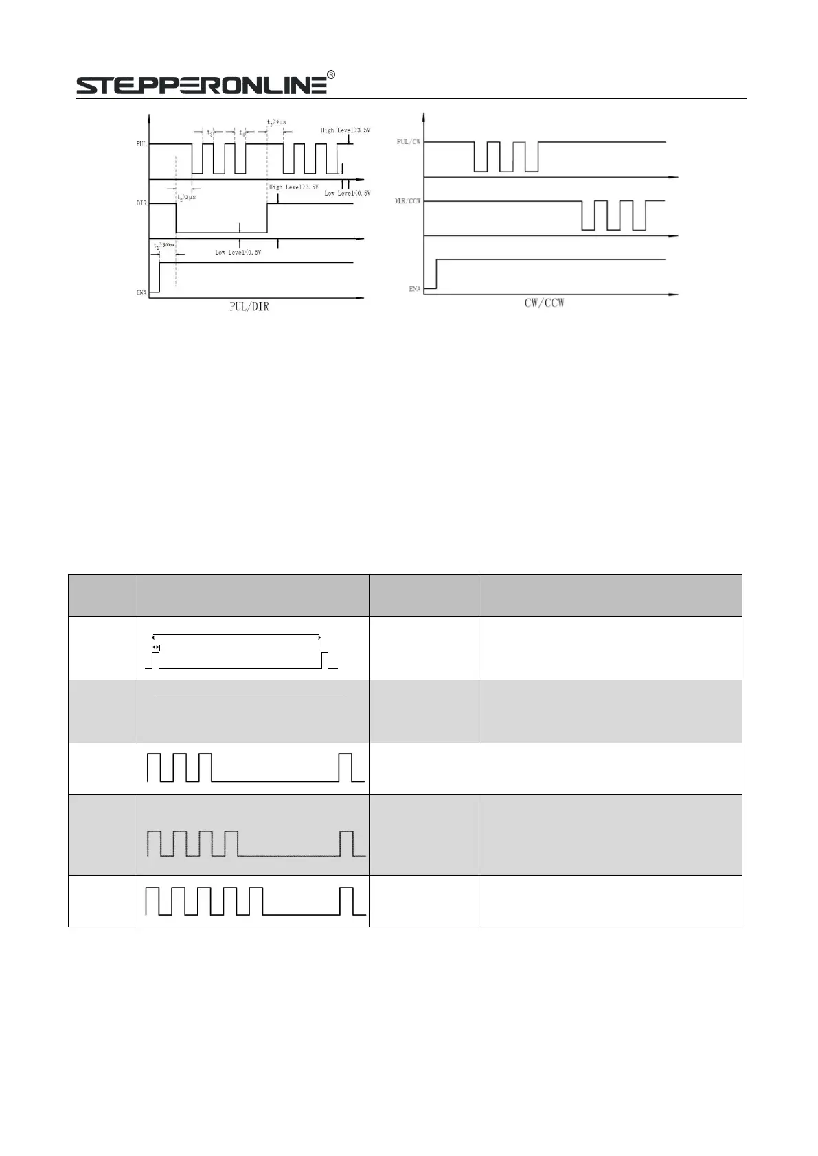
Figure 10: Sequence chart of control signals
Remark:
a)
t1: ENA must be ahead of DIR by at least 200ms. Usually, ENA+ and ENA- are NC (not connected).
See“Connector P1 Configurations” for more information.
b)
t2: DIR must be ahead of PUL effective edge by 2us to ensure correct direction;
c)
t3: Pulse width not less than 1us;
d)
t4: Low level width not less than 1us;
e)
Duty cycle of PUL signal is recommended 50%.
8.
Fault Protections & Troubleshooting
To improve reliability, the drive incorporates some built-in protection features.
Blink
time(s)
Sequence wave of red LED
Description Trouble shooting
1
5S
0.2S
Over-current
Turn off the power immediately.
a)
Check wiring is short-circuited or not;
b)
Check motor is short-circuited or not.
2
5S
0.3S 0.2S
Over-voltage
Turn off the power immediately.
a) Check if the power voltage is higher
than 90VDC
3
Chip error
Restart the power supply, if the drive
isstill alarm, please contact after-sale
4
Fail to lock
motor shaft
a)
The drive is not connected to a motor;
b)
If alarm is occurred when connect a
motor, please check the motor power
cable.
5
EEPROM error
Restart the power supply, if the drive
isstill alarm, please contact after-sale