CL42T(V4.1) Closed-Loop Stepper Driver
7
5.2.1
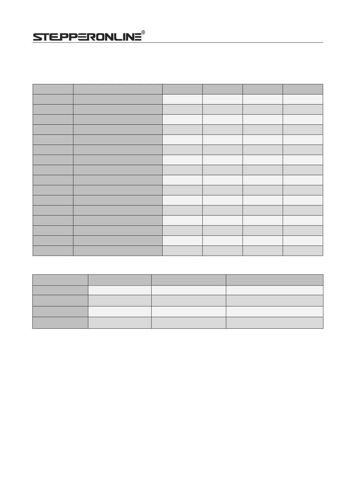
Micro Step (SW1-SW4)
Each CL42T(V4.1) has 16 microstep settings which can be configured through DIP switches SW1, SW2, SW3
and SW4.See the following table for detail.
Micro step Pulses/Rev. (for 1.8°motor)
SW1 SW2 SW3 SW4
1
200
on on on on
4
800
off on on on
8
1600
on off on on
16
3200
off off on on
32
6400
on on off on
64
12800
off on off on
128
25600
on off off on
256
51200
off off off on
5
1000
on on on off
10
2000
off on on off
20
4000
on off on off
25
5000
off off on off
40
8000
on on off off
50
10000
off on off off
100
20000
on off off off
200
40000
off off off off
5.2.2
Mode Setting (SW5 - SW8)
Function
ON OFF
SW5
Rotation Direction CW (clockwise) CCW (counterclockwise)
SW6
Control Mode Open loop control Closed loop control
SW7
Pulse Mode CW/CCW (double pulse)
PUL/DIR (single pulse)
SW8
Pulse Filter Time Yes (10ms) No (1.5ms)
CL42T(V4.1) has an advanced feature called Pulse Filter Time to make the input pulse from pulse generator
(controller,PLC, etc.) S-curve acceleration, to improve motion smoothness and high-speed start frequency in
manycircumstances.
The Filter Time value must be set to the same for each CL42T(V4.1) in multi-axis applications
5.3
S3 - Selector Switch Configurations
The 1-bit selector is located on the top (S3 in figure 2), used to configure the voltage of control signals. For the
safety of optically coupled, the factory setting is 24V, which no need to connect 2K resistors, making it easier to
use. Whenthe voltage of the control signal is 5V, the S3 must be set to 5V, otherwise, the motor won't work.