CL42T(V4.1) Closed-Loop Stepper Driver
4
Notes: (1) Shielding control signal wires is suggested;
(2)
To avoid/reduce interference, don’t tie control signal cables and power wires together;
(3)
Brake output need to connect a relay and diode
3.2
P2 - Encoder Signals Input Connector
The P2 connector in Figure 2 is for encoder signals connection. Refer to the following table for details.
Drive Pin Name
Description
EB+
Encoder B+ input connection
EB-
Encoder B- input connection
EA+
Encoder A+ input connection
EA-
Encoder A- input connection
VCC
Encoder +5V voltage output connection
EGND
Power ground connection
3.3
P3 - Motor Connector
PIN
Details
A+ Connect to motor A+ wire
A- Connect to motor A- wire
B+ Connect to motor B+ wire
B- Connect to motor B- wire
3.4
P4 - Power Connector
Pin
Details
GND Connect to power supply ground connection.
+VDC Connect to power supply positive connection. Suggest 24-48VDC power supply voltage
Warning: Don’t plug/unplug P3 or P4 connector to avoid drive damage or injury while powered on.
3.5
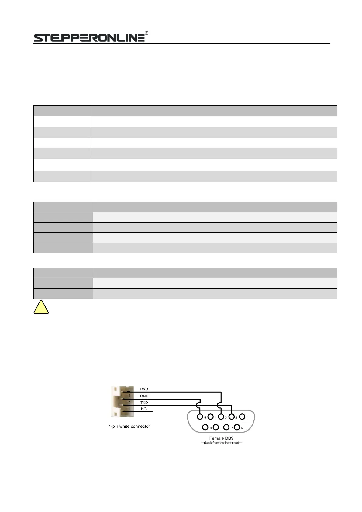
P5 – Debug Port
The P5 connector in Figure 2 is a RS232 communication port for PC connection. Refer to the following pin
definitions.CL42T has a tuning port with RS232 to modify the drive parameters; it is just used to modify
parameter, not for equipment control because neither precision nor stability is sufficient.
The interface definition is as follows: