WORKSHOP MANUAL
3 - ASSEMBLY AND REMOVAL
EDITION
PAGE
17 /37
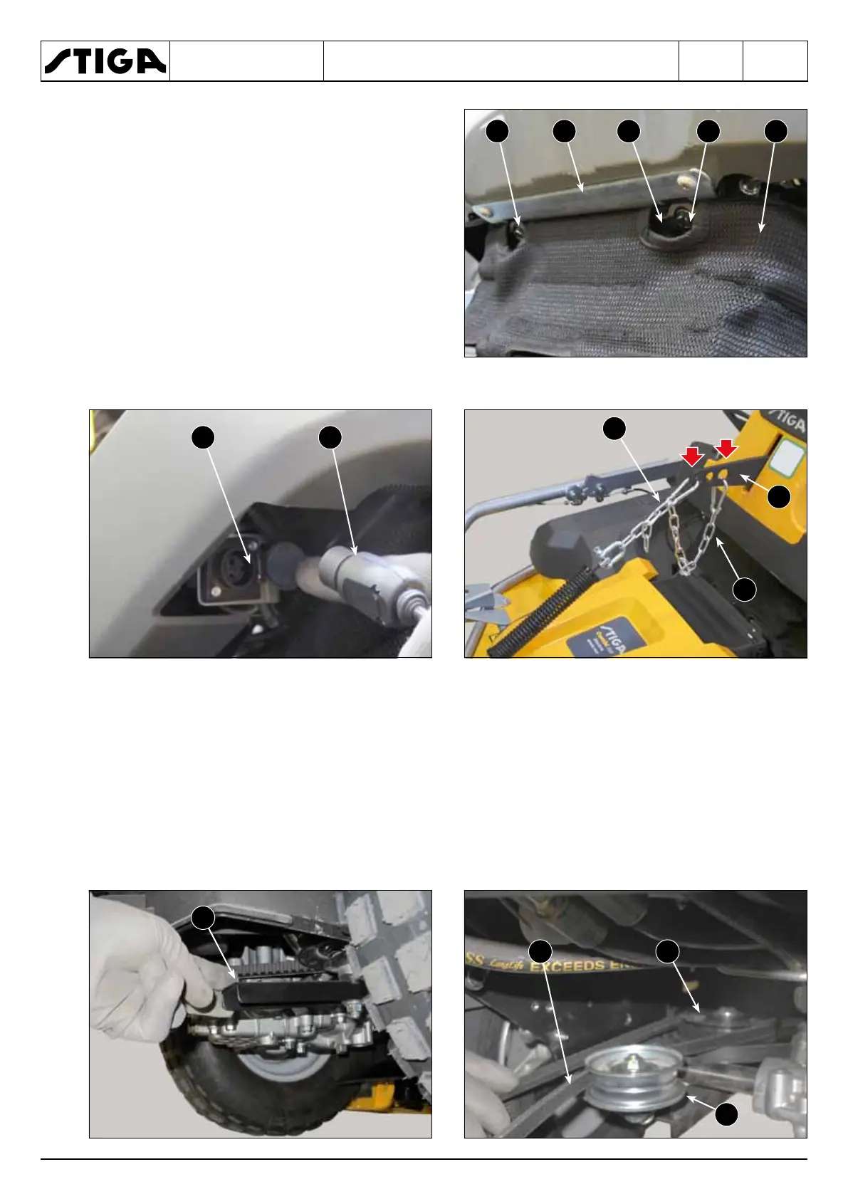
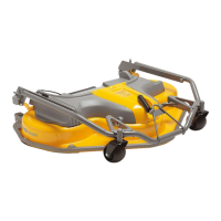
6. Position the guard (7) frame (9) in line with
the interface bracket (10) and fasten in place
with the two screws (11).
7. Connect the cutting height adjustment con-
trol coupling (12) to the plug (13) on the lower
right side of the machine.
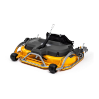
8. Keeping the front part of the deck slightly
raised, connect the spring clasp (14) to the
front hole and the safety chain (15) to the rear
hole of the machine lifting lever (16).
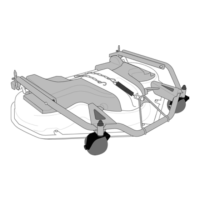
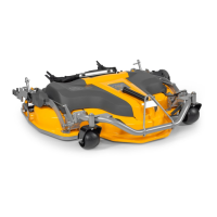
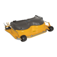
1. Pull the lever (1), located in the lower right part of the machine, outwards so as to distance it
from the tensioner (2).
2. Wrap the PTO belt (3) onto the pulley (4) making sure that the left branch remains inside the
tensioner (2).
3.
Disengage the lever (1).