WORKSHOP MANUAL
4 - MAINTENANCE
EDITION
PAGE
31 /37
• Remove the relevant blade
.
• Remove the relevant pulley from 1 to 2.
• Remove the central pulley and the toothed wheel of the locking device from 1 to 3.
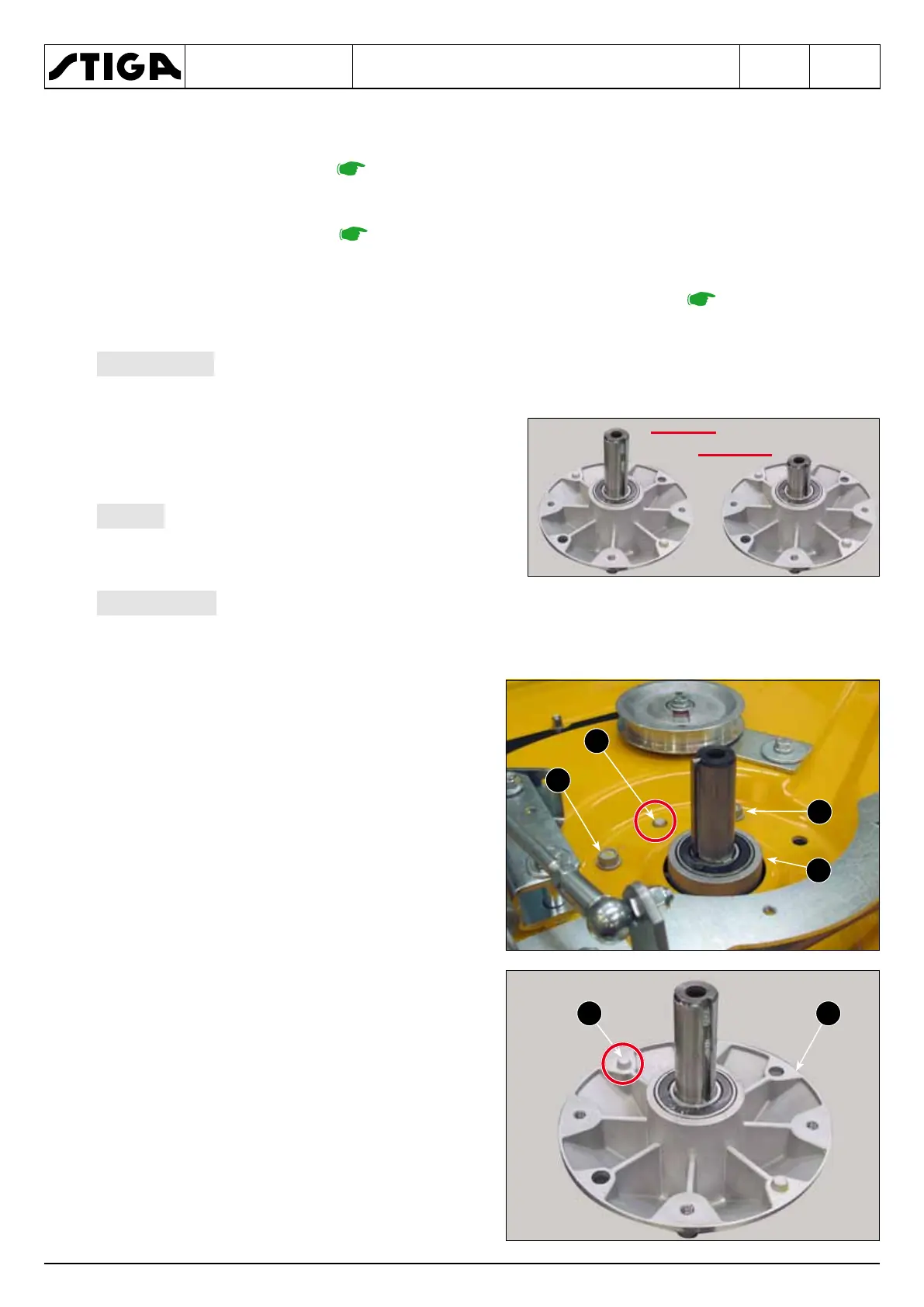
The supports, each complete with shaft and bearings, are available as spare parts
for two different assemblies:
• Short shaft on pulley side = Right or left support.
• Long shaft from the pulley side = Central sup-
port.
The bearings are of the airtight shielded
type and do not require lubrication.
The replacement of the shaft or of the bearings is an operation NOT foreseen by
the Manufacturer and therefore it must NEVER be proposed or performed autonomously by the
Support Centres.
1. Undo the four screws (1) fastening each sup-
port (2) and remove it from inside the cutting
deck.
When assembling, take care to position the two
centring pegs (3) in the respective holes provided
on the support surface.
Tighten the screws (1) using a torque wrench set
to 25-30 Nm.