BGA 8610
6.5 Removing the Inlet Cone
N Remove the blower, @ 6.4.
N Pull the inlet cone (13) off the blower (12).
N Remove the outlet cone, @ 8.2.
N Disassemble the blower, @ 8.4.
6.6 Removing Left Handle Housing
N Remove the controls, @ 7.
N Remove blower (12) with inlet cone (13), @ 6.4.
N Remove the screen (14).
N Remove the electrical components, @ 9.
N Locate the locking tabs inside the handle housing (3)
and push off the cover (2).
N Lift the handle molding (1) slightly at the locking tabs
and take it away.
N Remove the soundproofing (4).
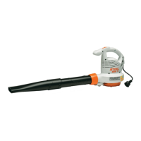
6.7 Installing Left Handle Housing
N Push the cover (2) into the guides on the handle
housing (3) until the locking tabs (arrows) snap into
place.
N Push the handle molding (1) against the handle
housing (3) until the locking tabs (arrows) snap into
place.
N Fit the soundproofing (4) so that its cutouts engage
the tabs on the handle housing (3).
N Install the electrical components, @ 9.
N Push the screen (14) into the guide in the handle
housing (3) as far as stop.
N Install the controls, @ 7.
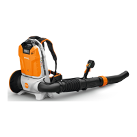
6.8 Installing the Inlet Cone
N Assemble the blower, @ 8.7.
N Install the outlet cone, @ 8.3.
N Push the inlet cone (13) onto the blower (12) so that
te marks (arrows) are in alignment.
N Install the blower tube, @ 6.9.
N Install the blower, @ 6.10
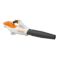
6.9 Installing the Blower Tube
N Fit the nozzle (6) on the blower tube (5).
N Push the blower tube (5) over the outlet cone (19) so
that the recess (arrow) engages the cable guide.
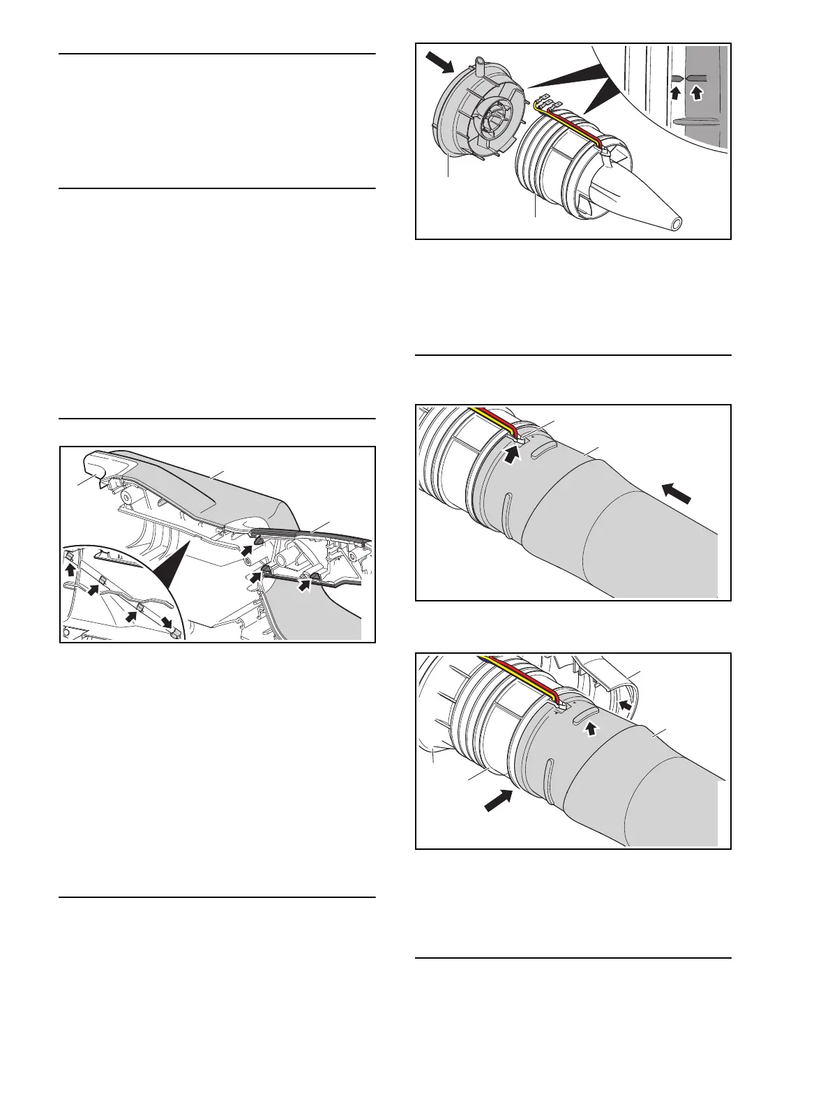
N Fit blower tube (5, 6) with blower (12) and inlet cone
(13). The bead (arrow) engages the seat (arrow) in
the left handle housing (3).
N Install right handle housing (11), @ 6.11.
6.10 Installing the Blower
N Install the outlet cone, @ 8.3.
N Install the inlet cone, @ 6.8.
 Loading...