BGA 86 19
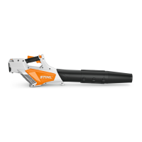
N Push connector (8) into the socket as far as stop.
N Completely cover connector (8) and wires with
multipurpose grease (see arrow).
N Position wires with protective tube in the guide
(arrow) on the left switch housing (1).
N Push the right switch housing (3) into the left switch
housing (1) so that the retaining tabs snap into place.
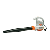
N Fit switch housing (1, 3) with switch in the left handle
housing.
N Install right handle housing, @ 6.11.
9.4 Removing the Contact Plate
N Preparations, @ 2.4.
N Remove right handle housing, @ 6.2.
N Remove the screen, @ 6.6.
N Pull the contact plate (6) out of the left handle
housing.
N Remove the spring (7).
N Raise the locking tabs (arrows) and lift the contact
plate (5) away.
N Pull the blade terminals (16) out of the contact plate
(6).
N Inspect blade terminals, replace electronic module (4)
if necessary, @ 9.6.
9.5 Installing the Contact Plate
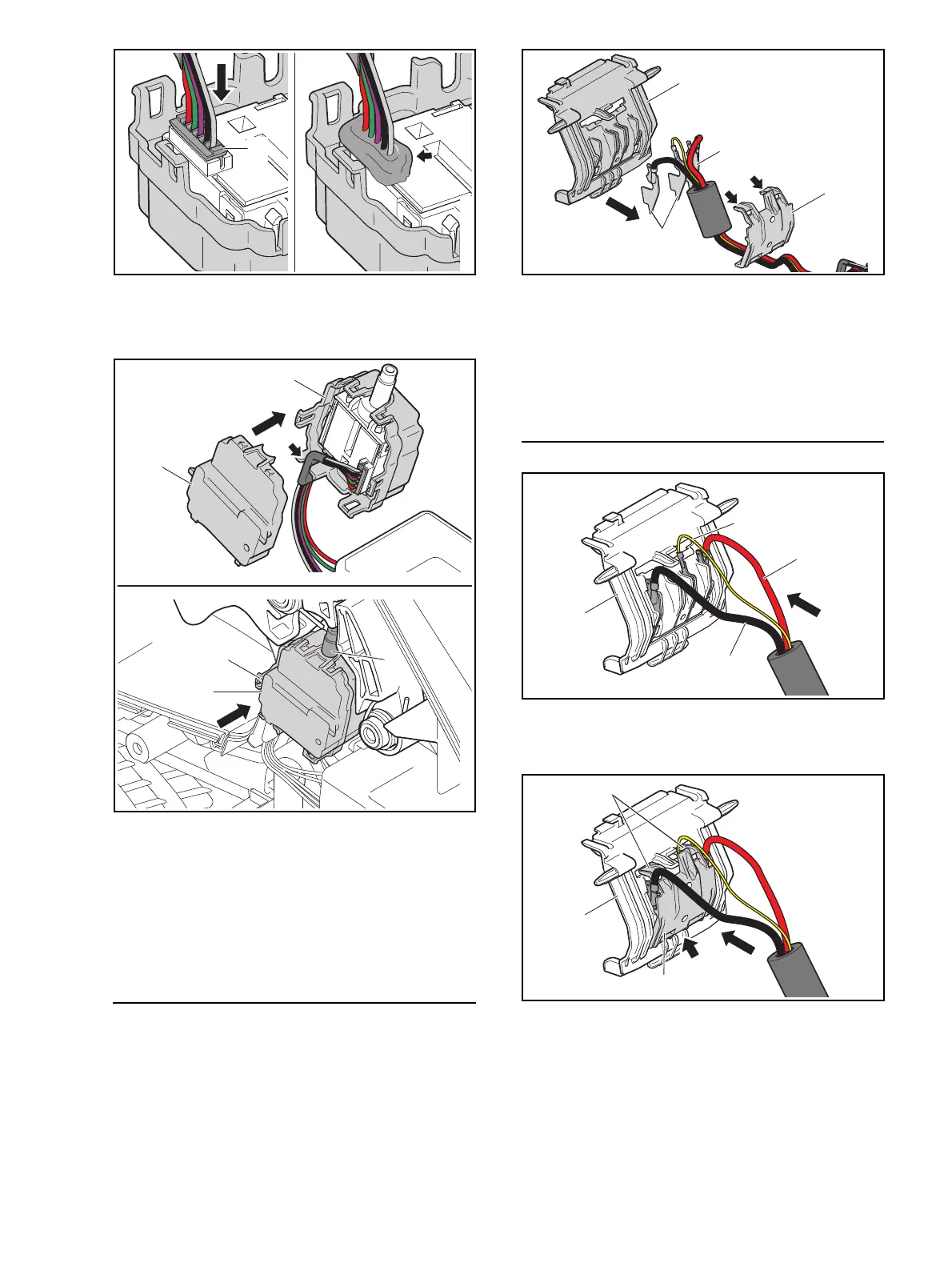
N Insert blade terminals of black wire (9), yellow wire
(10) and red wire (11) in the slots in the contact plate
(6) and hold them there.
N Push contact plate (5) into slot (arrow) in contact plate
(6).
N Push contact plate (5) with locking tabs (12) into
contact plate (6) so that the tabs snap into place.
Make sure the yellow wire is not pinched.
N Fit the spring (7) in the contact plate (6).
N Push contact plate (6) with pivots into the bores in the
left handle housing.

 Loading...