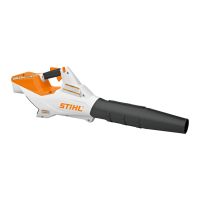
BGA 8620
N Push the wires and ferrite sleeve into the guides and
seat (arrows).
N Fit the screen, @ 6.7.
N Install right handle housing, @ 6.11.
9.6 Removing the Electronic Module
N Preparations, @ 2.4.
N Perform test with ADG 2 Analyzer, @ 5.
N Remove right handle housing, @ 6.2.
N Remove the blower tube, @ 6.3.
N Remove the blower, @ 6.4.
N Remove the switch, @ 9.2.
N Remove the contact plate, @ 9.4.
N Pull receptacles of yellow wire (YE), blue wire (BU)
and red wire (RD) out of the guides in the handle
housing.
N Pull the wires out of their guides.
N Pull the electronic module (4) out of its seat in the left
handle housing.
9.7 Installing the Electronic Module
N Position the electronic module (4) in its seat in the left
handle housing.
N Insert receptacle of yellow wire (13) in the guide (YE).
N Insert receptacle of blue wire (14) in the guide (BU).
N Insert receptacle of red wire (15) in the guide (RD).
N Push the wires and ferrite sleeve into the guides and
seat (arrows).
N Push the ferrite sleeve intoits seat (arrow).
N Push the red wire (17), yellow wire (18) and black wire
(19) into the guides (arrows) in that order.
N Fit the screen, @ 6.7.
N Install the switch, @ 9.2.
N Install contact plate, @ 9.5.
N Install the blower tube, @ 6.9.
N Install the blower, @ 6.10.
N Install right handle housing, @ 6.11.

 Loading...