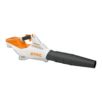
BGA 86 13
7.6 Installing the Retaining Latch
N Push the flat spring (5) into the guides (arrows) in the
left handle housing as far as stop.
N Fit the retaining latch (3) on the pivot in the left handle
housing so that the flat spring (5) is between the ribs
on the retaining latch (3).
N Fit the torsion spring (4) in the retaining latch (3),
making sure the legs (arrows) locate against the
retaining latch (3) and the rib in the left handle
housing. The torsion spring (4) is now pretensioned.
7.7 Installing the Trigger
N Install the retaining latch (3), @ 7.3.
N Fit the trigger (6) on the pivot in the left handle
housing so that it engages the retaining latch (3).
N Fit the torsion spring (7) in the trigger (6), making sure
the legs (arrows) locate against the trigger (6) and the
rib in the left handle housing. The torsion spring (7) is
now pretensioned.
N Place the switch housing (2) with switch (1) in its seat
in the left handle housing.
7.8 Installing the Ergo Lever
N Push the torsion spring (4) onto the pivot in the left
handle housing so that its bent leg engages the seat
(arrow).
N Place ergo lever (9) on the pivot in the left handle
housing and fit the long leg of torsion spring (4) in its
seat (12). The pin (13) is under the flat spring (5).
N Check operation of ergo lever, trigger and retaining
latch, @ 7.9.
N Install right handle housing, @ 6.11.
7.9 Checking Operation of Ergo Lever, Trigger and
Retaining Latch
Check operation of ergo lever and retaining latch:
N Operate the ergo lever (9) and push retaining latch (3)
in direction of blower tube. The retaining latch (3) is
held in position by the tensioned flat spring (5).
N Release the ergo lever (9). The retaining latch (3)
springs back to its idle position.

 Loading...