20 Series 4144 Components FC, FS, KM
5.9 Short Circuit Wire
5.9.1 Testing
If the spark plug, ignition lead and
spark plug boot are in order, check
the short circuit wire.
– Remove the shroud, b 5.1
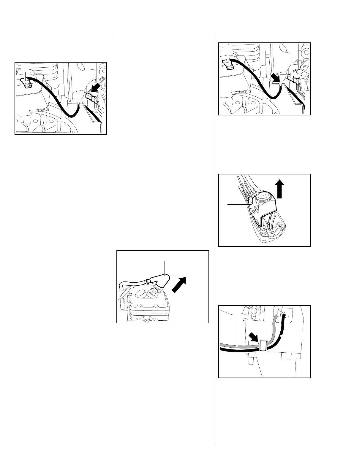
: Disconnect the short circuit wire
(1).
– Connect the ohmmeter to ground
(arrow) and the short circuit wire
(1).
– Set the stop switch to "
0" and
hold it in that position.
The resistance measured must be
about 0 Ω. If it is much higher, the
reason may be the stop switch or
the wire. Damaged parts must be
replaced, b 5.9.2, b 5.9.3.
– Release the stop switch.
The resistance measured must be
infinitely high. If not, fit a new short
circuit wire or stop switch, b 5.9.2,
b 5.9.3.
545RA057 TG
1
To locate the fault, test the wires for
continuity and check insulation for
damage. If the wires are in order,
check operation of stop switch,
b 5.10
If no fault can be found, check the
ignition system with the aid of the
troubleshooting chart, b 5.10.
– Check ground wire for continuity.
– Reassemble in the reverse
sequence.
5.9.2 Removing and Installing
(Loop Handle Version)
Separate short circuit (black) and
ground (blue) wires are installed in
these machines and may be
replaced individually in case of
damage.
– Remove the drive tube, b 9.1
– Remove the shroud, b 5.1
: Pull boot (1) off the spark plug.
545RA008 TG
1
: Disconnect the short circuit wire
(1) and ground wire (2).
– Pull the short circuit wire out of
the guide (arrow).
– Press down the interlock lever to
disengage it from the throttle
trigger.
: Pull out the support (1).
: Take the short circuit wire (1)
and ground wire (2) out of the
guide (arrow).
545RA058 TG
1 2
1
545RA059 TG545RA060 TG
1
2
 Loading...