43Series 4144 Components FC, FS, KM
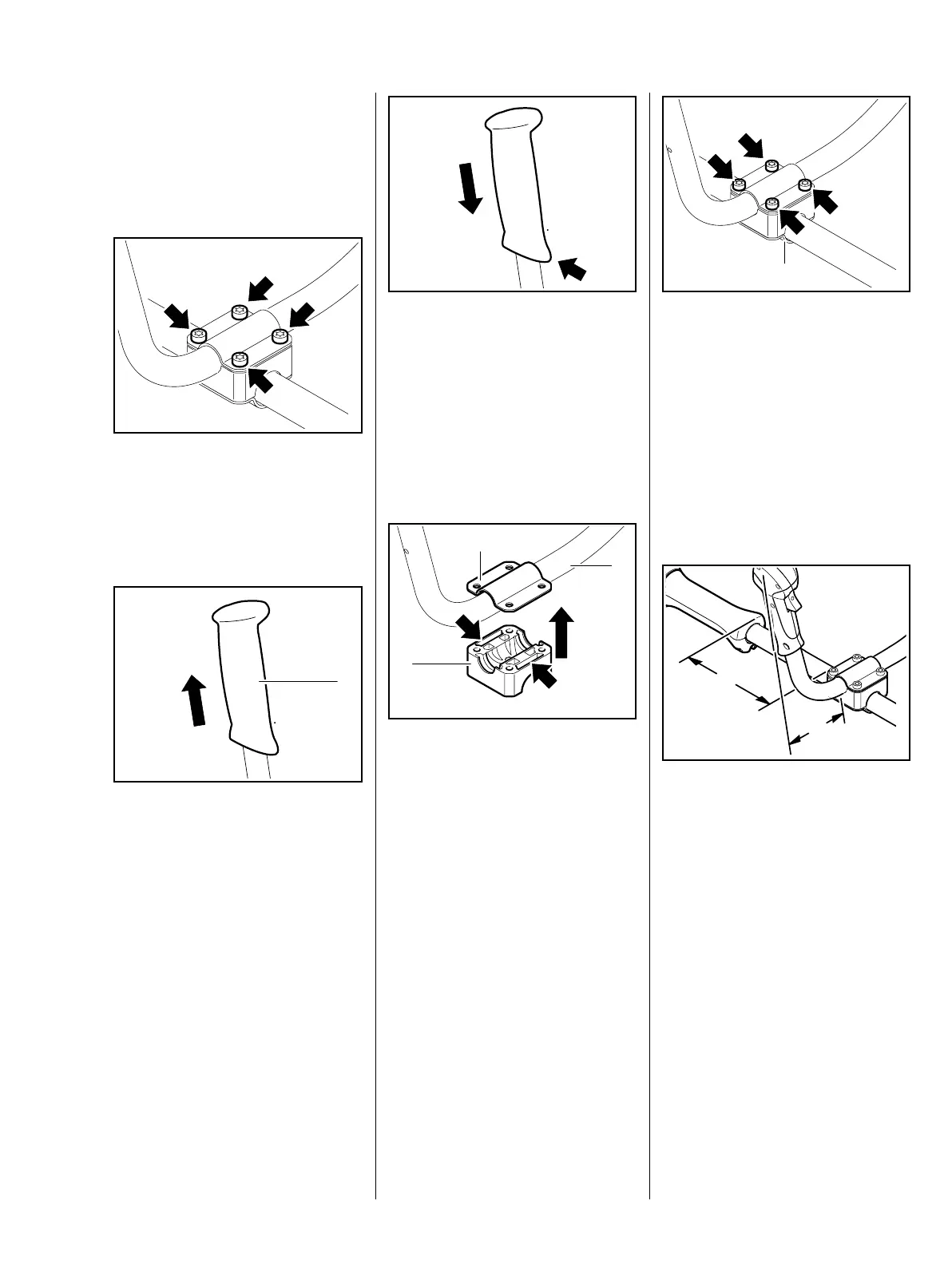
7.5 Handlebar
(Bike Handle)
– Remove the control handle,
b 5.9.3
: Take out the screws (arrows).
Handlebar and lower clamp drop
down after the screws have been
removed.
– Check the handle (1) and replace
if necessary
: Pull off the handle (1).
– If the handle is stuck, carefully cut
it open longitudinally at the
thinnest point.
545RA165 TG545RA166 TG
1
– Line up the handle so that its long
side (arrow) faces the cutting
tool.
The handle must be fitted in the dry
condition.
: Push the handle on to the
handlebar as far as stop.
The diameters of the handlebar and
drive tube are different.
: Position the clamp (1) with plain
holes against the handlebar (2).
: Position the clamp block (3), slots
(arrows) facing up, against the
underside of the handlebar.
– Insert the screws through the
clamp and clamp block.
545RA167 TG
545RA168 TG
2
1
3
– Position the preassembled
handlebar on the drive tube.
– Fit the clamp (1), with tapped
holes, against the underside of
the drive tube.
: Fit the screws (arrows)
– tighten them down only
moderately at this point to allow
for alignment.
– Swing handlebar upright, i.e. at
an angle of 90° to the drive tube.
– Line up the handlebar so that the
control handle is closer to the
drive tube.
: Adjust distance from engine
housing
a = about 20 cm
b = about 15 cm
– Tighten down the screws firmly.
545RA169 TG
1
a
b
545RA170 TG
 Loading...