42 Series 4144 Components FC, FS, KM
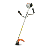
: Fit the torsion spring (1) on the
throttle trigger and attach its loop
to the boss (arrow).
: Rotate the leg clockwise and
engage it on the lever (arrow).
The ground and short circuit wires
must be properly seated in the
guides (arrows).
545RA159 TG
1
545RA160 TG545RA161 TG
: Push the throttle cable (1) and
protective tube (2) into the seats
(arrows) and hold in that position.
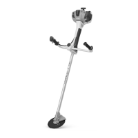
– Carefully fit the handle molding
(1) so that it snaps into position
– the levers may pop out.
: Insert screws (arrows) and
tighten them down firmly.
– Check operation.
The throttle trigger (2) must be
locked in position when the interlock
lever (1) is not depressed.
545RA162 TG
1
2
545RA146 TG
1
545RA006 TG
2
1
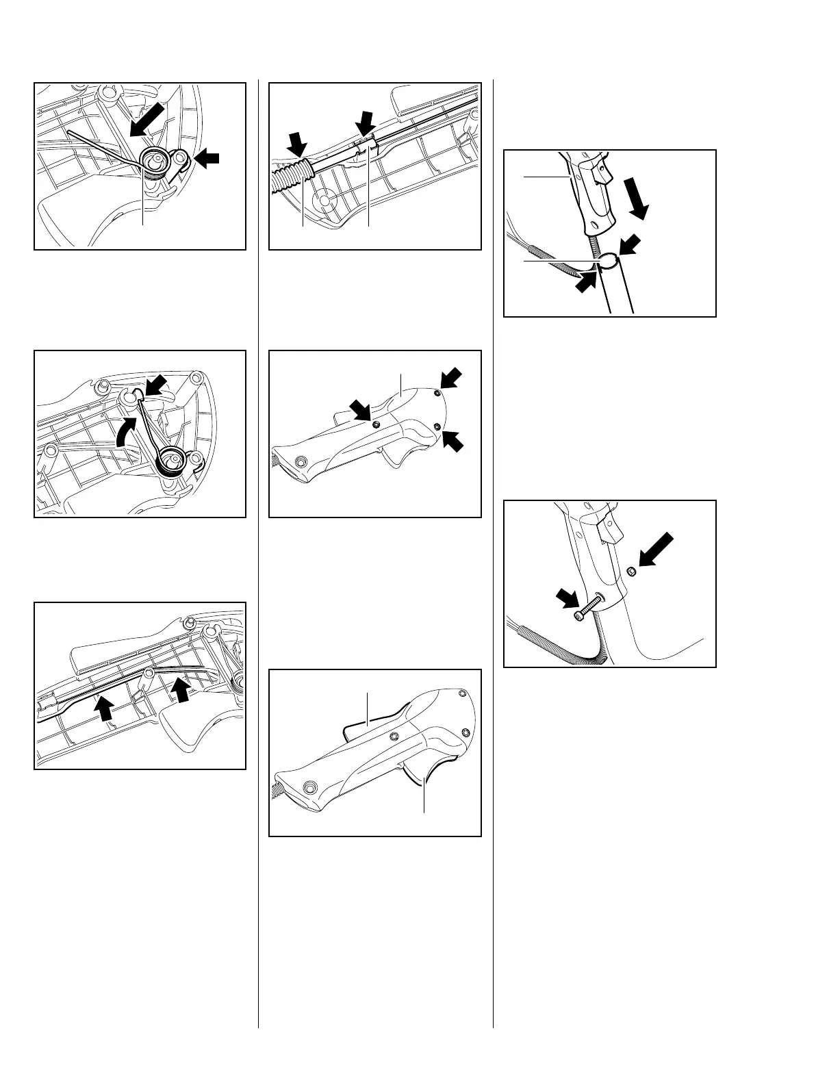
: Release the throttle trigger (2) – it
must return to the stop
– Line up the control handle (1) so
that the throttle trigger points
towards the coupling sleeve.
: Push the control handle (1) onto
the handlebar (2), turning it back
and forth until it engages the slots
(arrows).
– Fit the screw (arrow) through the
control handle and handlebar.
: Fit a new hex nut in the seat on
the other side and then tighten
down the screw firmly.
The control handle must be firmly
seated on the handlebar and not
move.
545RA163 TG
1
2
545RA164 TG
 Loading...