74 Series 4144 Components FC, FS, KM
– Install the drive tube, b 9.1
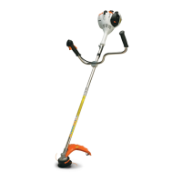
: Position the loop handle (1) at a
distance of about 5 cm (a) in
front of the engine housing.
– Line up the loop handle (1) so
that the barrier bar is opposite the
throttle trigger and tighten down
the screw (arrow) firmly.
9.2 Add-On Components
9.2.1 Deflector for Machines
without Gearbox
: Take out the clamp screw (arrow)
and remove the hex nut.
– Pull off the deflector (1).
1
545RA265 TG
a
545RA266 TG
1
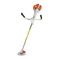
: Take out the screw (1).
: Pull off the clamp (2).
– Reassemble in the reverse
sequence.
– Inspect the bearing housing (3)
and replace if necessary,
b 9.1.5
: Take out the screw (arrow).
– Remove the line limiting blade
(1), check and sharpen or replace
as necessary.
1
2
545RA267 TG
3
1
545RA268 TG
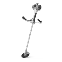
: Push the line limiting blade (1)
into its seat (arrow).
– Insert screw and tighten it down
firmly.
To avoid stripping the thread in the
plastic housing, carefully locate
screw in existing thread and tighten
in down.
– Reassemble all other parts in the
reverse sequence.
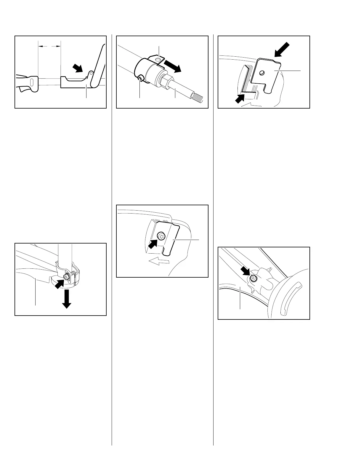
9.2.2 Deflector for Machines
with Gearbox
: Take out the screw (arrow).
– Remove the deflector (1).
1
545RA286 TG
1
545RA269 TG
 Loading...