38 Series 4144 Components FC, FS, KM
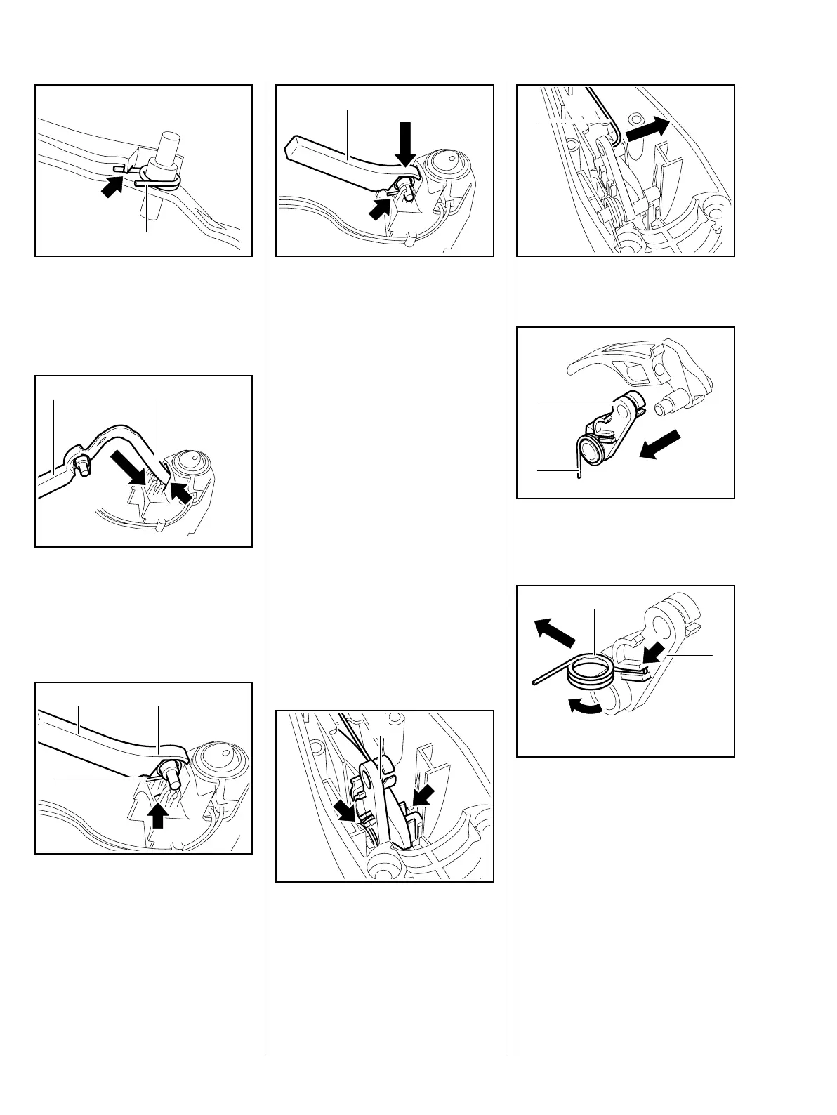
: Fit the torsion spring (1) in the
interlock lever so that its leg
(arrow) engages the recess as
shown (arrow).
: Push the interlock lever (1), arm
(2) first, into the opening (arrow)
and turn it slightly back and forth
to maneuver it past the stop
switch.
: Position the interlock lever (1) on
the mounts so that it faces up as
shown (2).
: Line up the torsion spring (3) so
that its leg locates against the lug
(arrow).
545RA130 TG
1
545RA131 TG
21
545RA132 TG
2 1
3
: Press the interlock lever (1) into
the mounts until it snaps into
place.
– The leg of the torsion spring must
locate against the edge (arrow) of
the support and project slightly.
– Install the support and fit the
short circuit wire in the guide,
b 5.9.2
– Check operation
– the throttle trigger is locked
when the interlock lever is not
depressed.
– Reassemble all other parts in the
reverse sequence.
– Tightening torques, b 3.4
7.3.1 Throttle Trigger
– Remove the support with
interlock lever, b 7.3
: Ease the throttle trigger (1) out of
its mounts (arrows).
545RA133 TG
1
545RA134 TG
1
: Disconnect the throttle cable (1).
: Pull off the lever (1) with torsion
spring (2).
: Turn the torsion spring (1) and
pull it out of the guide (arrow).
– Check the lever (2) and torsion
spring (1) and replace if
necessary
545RA135 TG
1
545RA136 TG
2
1
545RA137 TG
1
2
 Loading...