22 Series 4144 Components FC, FS, KM
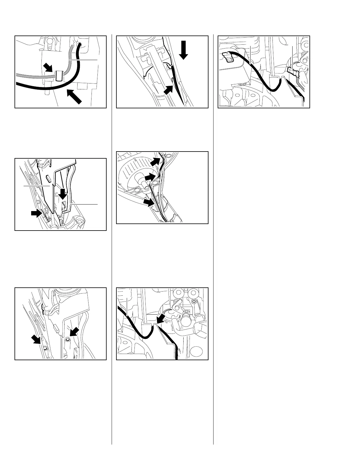
: Fit the wires, ground wire (1) first,
in the guide – position the wires
next to one another without
loops.
: Push the support (1) into position
so that the tabs engage the
guides (arrows) and the interlock
lever (2) engages the underside
of the throttle trigger.
: When pushing the into position,
check that its pegs engages the
holes (arrows).
545RA067 TG
1
545RA068 TG
1
2
545RA069 TG
: Push the support fully home and
position the wires, short circuit
wire first, in the guide (arrow).
: Push the short circuit into the
guides (arrows) first, then the
ground wire.
Lay the wires next to one another
without crossing over.
: Fit the short circuit wire (1) in the
guide (arrow).
545RA070 TG545RA094 TG545RA071 TG
1
: Push short circuit wire (1) and
ground wire (2) firmly onto the
connector tags.
– Reassemble all other parts in the
reverse sequence.
– Tightening torques, b 3.4
– Check operation.
545RA045 TG
1
2
 Loading...